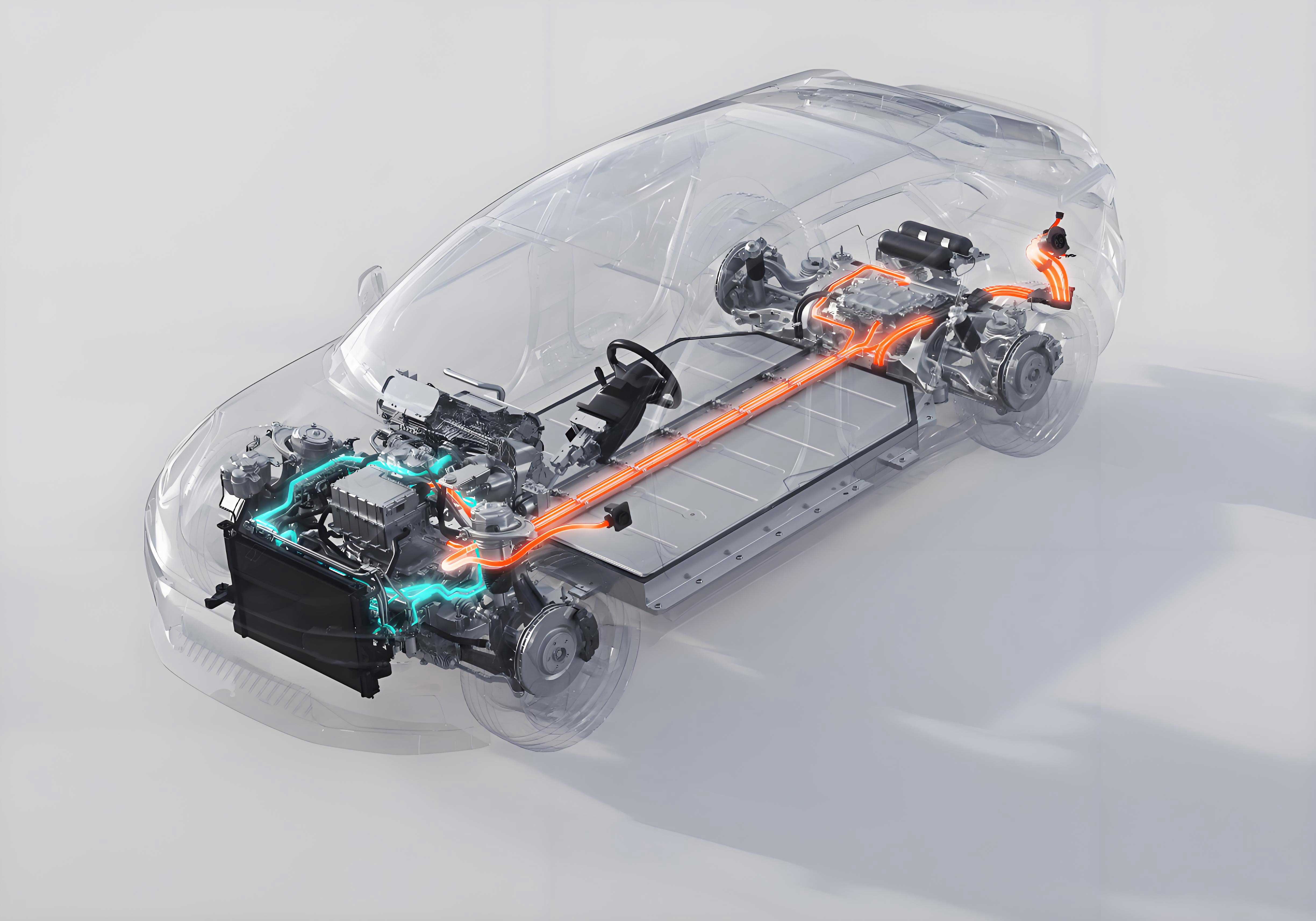
As a researcher specializing in automotive thermal systems, I present a comprehensive analysis of thermal comfort in electric vehicles (EVs), integrating global research advances, predictive modeling, and optimization strategies. The unique energy constraints of EVs—where HVAC systems consume up to two-thirds of battery capacity—demand solutions that balance occupant comfort with range preservation. This review synthesizes key findings and proposes data-driven pathways for innovation.

1. Critical Factors Influencing EV Cabin Thermal Comfort
EV cabins exhibit transient and non-uniform thermal environments due to rapid temperature fluctuations and spatial variability. Four environmental parameters dominate:
1.1 Air Temperature (T<sub>a</sub>)
Non-uniform T<sub>a</sub> distribution causes local discomfort (e.g., warm torso/cold feet). Studies show segmented HVAC zones improve personal comfort while reducing energy use by 15–20%:
\Delta E = Q_{\text{HVAC}} \times \eta^{-1} \quad \text{where} \quad \eta = 0.8–0.9
Table 1: Thermal Asymmetry in EV Cabins
| Location | ΔT<sub>a</sub> vs. Occupant (°C) | Comfort Impact |
|---|---|---|
| Front Row | +3.5 to +5.2 | Overheating |
| Rear Row | -1.8 to -3.0 | Draft Sensation |
| Footwell | -2.5 to -4.0 | Local Cooling |
1.2 Air Velocity (v<sub>a</sub>)
Optimal v<sub>a</sub> = 2–5 m/s enhances convective heat transfer. Beyond 5 m/s, draught sensation (PD > 20%) occurs. Energy trade-off is quantified by:
\text{Comfort Gain} = 60\% \times \Delta v_{a}; \quad \text{Energy Penalty} = 4.5\% \times \Delta v_{a}
1.3 Relative Humidity (RH)
RH > 60% impedes evaporative cooling; RH < 40% causes mucosal dryness. Dual control of T<sub>a</sub> and RH accelerates comfort attainment by 30% versus T<sub>a</sub>-only strategies.
1.4 Solar Radiation (G<sub>s</sub>)
Solar load contributes 70% of cabin heat gain. Surface temperatures exceed 73°C, raising T<sub>a</sub> by 8–12°C. The net heat flux is:
q_{\text{solar}} = \alpha \tau G_{s} \quad \text{(α = absorption; τ = transmittance)}
1.5 Personal Factors
Metabolic rate (1.0–1.3 met), clothing insulation (0.5–1.0 clo), age, and gender cause ±0.8°C tolerance variance. Adaptive models must incorporate real-time biometric feedback.
2. Thermal Comfort Modeling for Electric Vehicles
2.1 Physiological Models
- Two-Node Model (Gagge): Simplifies thermoregulation into core (T<sub>c</sub>) and skin (T<sub>sk</sub>) nodes:math复制下载\frac{dT_{c}}{dt} = M – q_{\text{resp}} – q_{\text{evap}} – q_{\text{conv}} Valid for t < 60 min exposure.
- Fiala Model: Integrates passive (heat exchange) and active (vasoconstriction/sweating) systems. Predicts T<sub>c</sub> with <0.2°C error.
- Berkeley Model: 16-segment body division enables localized comfort prediction. Validated for EVs with radiative heaters, reducing HVAC load by 10%.
2.2 Psychological Models
- PMV-PPD (Fanger):math复制下载\text{PMV} = f(T_{a}, v_{a}, \text{RH}, \bar{T}_{\text{rt}}, I_{\text{cl}}}) \quad \text{and} \quad \text{PPD} = 100 – 95e^{-(0.03353\text{PMV}^4 + 0.2179\text{PMV}^2)} Limitations: Underpredicts discomfort in non-uniform EV environments.
- Localized Comfort (Zhang): Correlates segmental skin temperature (T<sub>sk,seg</sub>) with overall comfort (R<sup>2</sup> = 0.89).
- Machine Learning (Lee): Personalized OS models using IR heater data improve prediction accuracy by 2.6× versus PMV.
3. Energy-Efficient Optimization Strategies
Table 2: Optimization Measures for EV Thermal Comfort
| Component | Technology | Comfort Improvement | Energy Saving |
|---|---|---|---|
| Windows | Cholesteric LC Reflector Film | ΔT<sub>surface</sub> = -15°C | 60% solar load ↓ |
| Seats | Zonal IR Heating | T<sub>a</sub> tolerance +4°C | 10–12% HVAC ↓ |
| Ventilation | Angled Outlets (30°–50°) | PPD reduction 20–30% | 20.8% fan energy ↓ |
| Radiation | Hybrid IR-Convection System | Local TSV = +0.8 | 8.5% peak load ↓ |
3.1 Solar-Reflective Windows
Cholesteric polymer bilayer films reflect 95% of IR radiation while maintaining >80% visible transmittance. Implementation cuts cabin soak temperatures by 12–18°C.
3.2 Active Seat Systems
Heated seats elevate acceptable T<sub>a</sub> from 21°C to 25°C, reducing HVAC duty cycle. Zonal heating targeting thermosensitive areas (lower back/thighs) boosts range by 1.5%.
3.3 Ventilation Geometry Optimization
CFD-validated outlet angles (30° horizontal/50° vertical) minimize draft risk (PD < 10%) while lowering fan power:
\dot{W}_{\text{fan}} \propto \Delta P \cdot \dot{V} \quad \text{where} \quad \Delta P \downarrow 35\% \ \text{@} \ 30^\circ
3.4 Radiative Heating
IR panels (λ = 5–20 μm) directly warm occupants without convective losses. Combined with heat pumps, COP increases from 2.1 to 3.0.
4. Future Directions: Balancing Comfort and Range
The electric vehicle industry must address:
- Predictive Control: ML algorithms using cabin occupancy, biometrics, and ambient forecasts to pre-condition cabins.
- Phase-Change Materials (PCMs): Latent heat storage (ΔH = 150–220 kJ/kg) buffers thermal transients.
- Localized Microclimate Systems: Energy use per zone < 100W vs. 3–5 kW for full HVAC.
Conclusion
Thermal comfort in electric vehicles necessitates interdisciplinary innovation. Physiological-psychological hybrid models, coupled with energy-aware technologies like selective glazing and radiative heating, can reduce HVAC loads by 25–40%. This extends EV range by 12–18% while maintaining PMV ±0.5. As EVs dominate sustainable transport, optimizing cabin efficiency remains paramount—not merely for comfort, but for viability in a range-constrained future.
