
The pursuit of efficient and robust propulsion systems is central to advancing battery electric car technology. At the heart of this propulsion lies the electric motor drive, with the Permanent Magnet Synchronous Motor (PMSM) being a predominant choice due to its high power density and efficiency. However, achieving precise and resilient speed control for a PMSM in a battery electric car presents significant challenges. The motor’s inherent nonlinear dynamics, combined with parameter uncertainties (e.g., variations in inertia, winding resistance) and external load disturbances (such as sudden changes in road grade or torque demand), can severely degrade the performance of conventional control strategies. The classical Field-Oriented Control (FOC) scheme, which employs Proportional-Integral (PI) regulators for current and speed loops, is widely used for its simplicity. Yet, its design often relies on linearized approximations of the motor model. When confronted with the full nonlinearities and real-world disturbances encountered by a battery electric car, the PI-based speed loop struggles to maintain desired transient response and steady-state accuracy, leading to potential instability or poor drivability.
To address these limitations inherent in controlling a battery electric car’s motor, this work proposes and investigates a control scheme based on the Nonlinear Active Disturbance Rejection Control (NLADRC) paradigm. The core objective is to replace the linear PI speed controller in the standard FOC structure with a specifically designed nonlinear controller that actively estimates and compensates for the total disturbance affecting the speed loop. This total disturbance amalgamates internal model uncertainties and external load torques. The proposed strategy aims to grant the speed regulation system of a battery electric car’s PMSM superior robustness and high-precision tracking capability without requiring an exact mathematical model of all nonlinearities and disturbances.
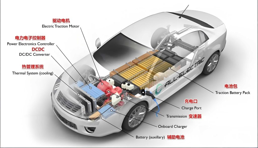
The efficacy and stability of any advanced control law for a safety-critical application like a battery electric car must be rigorously established. Therefore, beyond merely proposing the NLADRC structure, this research performs a comprehensive stability analysis. Crucially, this analysis incorporates the complete nonlinear electromechanical dynamics of the salient-pole PMSM, which is common in automotive applications for its high torque density. We demonstrate that the closed-loop system comprising the PMSM, the standard PI current controllers, and the novel NLADRC speed regulator is globally exponentially stable under the proposed control law. Finally, the theoretical claims are substantiated through experimental validation on a laboratory test bench emulating a battery electric car’s drive conditions. The performance of the proposed NLADRC-based system is systematically compared against the classical FOC with a PI speed controller under various scenarios, including speed reference tracking, step changes in system inertia, and application of external load torque disturbances.
Fundamentals of Nonlinear ADRC and PMSM Modeling
The proposed control architecture for the battery electric car’s motor is built upon the fusion of a robust outer-loop speed controller and the well-established inner-loop current control. The classical PI-based speed controller in FOC has a fundamental limitation: its transient response and disturbance rejection are coupled and tuned by the same set of parameters (\(k_p\), \(k_i\)). When a desired speed command \(R(s)\) is applied in the presence of an external disturbance \(D(s)\), no single tuning rule allows the system to simultaneously achieve an ideal transient response and perfect disturbance rejection. The Nonlinear Active Disturbance Rejection Controller is introduced to decouple these objectives and actively cancel out the effects of disturbances.
The general architecture of a two-degree-of-freedom NLADRC is depicted in the block diagram below. Here, \(P(s)\) represents the actual plant (the speed dynamics of the battery electric car’s motor), and \(P_n(s)\) is its nominal model used for design. The controller is composed of two main blocks, \(C_A(s)\) and \(C_B(s)\), designed based on a specified desired closed-loop model \(G_{ry}(s)\) and a filter \(Q(s)\) that governs disturbance rejection performance.
Following the design methodology, the filter \(Q(s)\) is chosen as a second-order Butterworth filter for a smooth frequency response:
$$ Q(s) = \frac{1}{1 + 1.414\tau_1 s + (\tau_1 s)^2} $$
For the speed control problem of a battery electric car’s drive, the nominal plant and the desired model are typically first-order systems. The nominal model represents the idealized mechanical dynamics, while the desired model dictates the closed-loop speed response time.
$$ P_n(s) = \frac{1}{J_n s + B_n}, \quad G_{ry}(s) = \frac{1}{\tau_r s + 1} $$
Here, \(J_n > 0\) and \(B_n > 0\) are the nominal moment of inertia and viscous friction coefficient of the battery electric car’s motor drive system, respectively. \(\tau_r > 0\) is the desired closed-loop time constant, and \(\tau_1 > 0\) is the filter time constant governing the bandwidth of disturbance estimation. Based on this framework, the controller transfer functions \(C_A(s)\) and \(C_B(s)\) are derived as:
$$ C_A(s) = \frac{ \frac{J_n}{\tau_r} s^2 + \left( \frac{1.414 J_n}{\tau_1 \tau_r} + \frac{B_n}{\tau_r} \right) s + \frac{1.414 B_n}{\tau_1 \tau_r} }{ \frac{1.414}{\tau_1} s } $$
$$ C_B(s) = \frac{ \frac{J_n}{\tau_1 \tau_r} s^3 + \left( \frac{J_n}{\tau_1^2 \tau_r} + \frac{1.414 B_n}{\tau_1 \tau_r} \right) s^2 + \left( \frac{1.414 B_n}{\tau_1^2 \tau_r} + \frac{1}{\tau_r} \right) s + \frac{1.414}{\tau_1 \tau_r} }{ \frac{1.414}{\tau_1} s } $$
The accurate control of a battery electric car’s PMSM necessitates a precise dynamic model. Using Park’s transformation, the standard \(dq\)-axis model of a PMSM is given by the following nonlinear equations:
Electrical Dynamics (\(d\)-axis):
$$ L_d \frac{dI_d}{dt} = V_d – R_s I_d + n_p \omega L_q I_q $$
Electrical Dynamics (\(q\)-axis):
$$ L_q \frac{dI_q}{dt} = V_q – R_s I_q – n_p \omega L_d I_d – n_p \omega \Phi_M $$
Mechanical Dynamics:
$$ J \frac{d\omega}{dt} = \tau_e – B \omega – T_L = \frac{3}{2} n_p \left[ \Phi_M I_q + (L_d – L_q) I_d I_q \right] – B \omega – T_L $$
where \(\omega\) is the rotor speed; \(I_d, I_q\) and \(V_d, V_q\) are the \(dq\)-axis currents and voltages; \(R_s\) is the stator resistance; \(L_d, L_q\) are the \(dq\)-axis inductances; \(n_p\) is the number of pole pairs; \(\Phi_M\) is the permanent magnet flux linkage; \(J\) is the total inertia (including the battery electric car’s motor and reflected load); \(B\) is the viscous friction coefficient; \(T_L\) is the load torque; and \(\tau_e\) is the electromagnetic torque. The term \((L_d – L_q)I_d I_q\) accounts for the reluctance torque, which is zero for a non-salient pole (surface-mounted) PMSM but significant for the interior PMSM (IPMSM) often used in battery electric cars for higher torque density.
Design and Stability Analysis of the NLADRC-Based Speed Regulation System
The complete speed control system for the battery electric car’s PMSM is implemented by embedding the NLADRC speed controller within the FOC framework. The inner \(dq\)-axis current loops are retained and regulated by fast PI controllers to ensure accurate tracking of the current references \(I_d^*\) and \(I_q^*\). The outer speed loop, which generates the \(q\)-axis current reference \(I_q^*\) (with \(I_d^*\) typically set to zero for maximum torque per ampere control in surface PMSM or optimally controlled in IPMSM), is where the NLADRC is applied. The block diagram of the complete system is shown conceptually in the previous figure.
Applying the inverse Laplace transform to the controller \(C_A(s)\) and \(C_B(s)\) with \(R(s)=\omega^*/s\) and \(Y(s)=\omega(s)\), the nonlinear ADRC speed control law in the time domain can be expressed as:
$$ u(t) = k_p \tilde{\omega}(t) + k_i \int_0^t \tilde{\omega}(\sigma) d\sigma + k_{ii} \int_0^t \int_0^\sigma \tilde{\omega}(\rho) d\rho d\sigma + k_{iii} \int_0^t \int_0^\sigma \int_0^\rho \tilde{\omega}(\lambda) d\lambda d\rho d\sigma – k_{pA} \omega(t) – k_{iA} \int_0^t \omega(\sigma) d\sigma – k_{iiA} \int_0^t \int_0^\sigma \omega(\rho) d\rho d\sigma $$
where \(\tilde{\omega} = \omega^* – \omega\) is the speed error. The gains \(k_p, k_i, k_{ii}, k_{iii}, k_{pA}, k_{iA}, k_{iiA}\) are constants derived from \(J_n, B_n, \tau_r,\) and \(\tau_1\). For implementation and stability analysis, this control law can be equivalently rewritten in a state-feedback form involving the speed error, its integrals, and estimates of disturbances. The control output \(u(t)\) is effectively the command for the electromagnetic torque, which is proportional to the \(q\)-axis current reference \(I_q^*\) via the torque constant.
Therefore, the complete current references for the inner loops are defined as:
$$ I_d^* = 0 $$
$$ I_q^* = \frac{u(t)}{\Phi_M} $$
The inner loop PI controllers then ensure that the actual currents \(I_d\) and \(I_q\) track these references rapidly. Combining the NLADRC law, the PI current controllers (which can be designed to have much faster dynamics than the speed loop), and the PMSM nonlinear model, we obtain the complete closed-loop system dynamics.
The global exponential stability of this interconnected nonlinear system for the battery electric car’s drive is proven using Lyapunov theory. The key steps involve:
- Defining a composite Lyapunov candidate function \(V\) that accounts for the speed error states (\(z_1, z_2, z_3\) related to integrals of \(\tilde{\omega}\)) and the current tracking errors (\(\xi_d = I_d – I_d^*\), \(\xi_q = I_q – I_q^*\)).
- Exploiting the fact that the inner current loops are designed to be exponentially stable, implying that \(\xi_d\) and \(\xi_q\) decay to zero rapidly.
- Showing that the time derivative of the Lyapunov function, \(\dot{V}\), is negative definite along the trajectories of the reduced-order system (where currents are at their references), given proper selection of NLADRC gains derived from \(\tau_r\) and \(\tau_1\).
- Using singular perturbation theory or similar arguments to conclude that the full system, with fast stable current dynamics and a stable speed error dynamics, is globally exponentially stable. This rigorous analysis ensures that the control system for the battery electric car’s motor will converge to the desired speed from any initial condition and remain stable despite the nonlinear coupling terms like \(n_p \omega L_q I_q\).
Experimental Validation and Performance Analysis
Experimental Platform and Controller Parameters
A laboratory test bench was constructed to emulate the traction system of a battery electric car and validate the proposed controller. The core of the system is a PMSM, whose nominal parameters are listed in Table 1. An auxiliary brushless DC (BLDC) motor is coupled to the PMSM shaft via a torque sensor. This BLDC motor acts as a programmable dynamic load, capable of applying step torque disturbances to simulate sudden changes in road load for a battery electric car. The control algorithms, including both the proposed NLADRC and the classical PI speed controller for comparison, were implemented on a Texas Instruments TMS320F28335 microcontroller. The switching and sampling frequencies were set to 10 kHz for the current loops and 2 kHz for the speed loop.
| Motor Parameter | Symbol | Value |
|---|---|---|
| Rated Power | \(P_{rated}\) | 400 W |
| Rated Phase Voltage | \(V_{rated}\) | 220 V |
| Rated Phase Current | \(I_{rated}\) | 2.7 A |
| Rated Speed | \(\omega_{rated}\) | 3000 rpm |
| Rated Torque | \(T_{L,rated}\) | 1.27 N·m |
| Number of Pole Pairs | \(n_p\) | 4 |
| Stator Resistance | \(R_s\) | 2.7 Ω |
| d-axis Inductance | \(L_d\) | 8.5 mH |
| q-axis Inductance | \(L_q\) | 8.5 mH |
| PM Flux Linkage | \(\Phi_M\) | 0.301 Wb |
| Nominal Inertia | \(J_n\) | 31.7 × 10⁻⁶ kg·m² |
| Nominal Viscous Friction | \(B_n\) | 52.8 × 10⁻⁶ N·m·s/rad |
When the BLDC motor is coupled without applying external torque, the total system inertia increases. The parameters for this configuration are shown in Table 2. This scenario tests the controller’s robustness to parameter variation, a common situation in a battery electric car where the effective inertia can change with vehicle loading.
| Parameter | Symbol | Value |
|---|---|---|
| Total Inertia | \(J_T\) | 167.1 × 10⁻⁶ kg·m² |
| Total Viscous Friction | \(B_T\) | 106.9 × 10⁻⁶ N·m·s/rad |
The parameters for the proposed NLADRC speed controller were designed for a desired closed-loop time constant \(\tau_r = 50\) ms and a disturbance filter time constant \(\tau_1 = 1.8\) ms, using the nominal parameters \(J_n\) and \(B_n\) from Table 1. For a fair comparison, the gains of the classical PI speed controller (\(k_{p\omega}\), \(k_{i\omega}\)) were tuned to achieve approximately the same 50 ms rise time under nominal conditions (no coupled BLDC motor).
Step Speed Command Tracking Performance
The first experiment evaluates the tracking performance under nominal conditions (PMSM alone, parameters as in Table 1). A step speed command from 0 to 1500 rpm was applied. The results, showing the actual speed \(\omega\) and the q-axis current \(I_q\), are depicted in the figure below. Both controllers achieved the desired steady-state speed. The NLADRC response precisely followed the first-order trajectory with the designed 50 ms time constant. The PI controller also showed a fast response but with a slight deviation from the ideal first-order curve, demonstrating the NLADRC’s superior ability to enforce the desired closed-loop dynamics. This precise tracking is vital for a battery electric car to respond accurately to driver acceleration commands.
Robustness to Parameter Uncertainty and Load Disturbance
The robustness of the controller for a battery electric car’s drive is critical. Two tests were conducted with the BLDC motor coupled, significantly increasing the system inertia to \(J_T \approx 5.2 J_n\) (Table 2).
Test 1: Inertia Variation without Load Torque. The speed step response was repeated. The NLADRC-based system maintained nearly identical transient and steady-state performance as in the nominal case, effectively rejecting the effect of the inertia change. In contrast, the PI-controlled system exhibited noticeable overshoot and a slower settling time because its fixed gains were no longer optimal for the altered plant dynamics. This highlights the NLADRC’s inherent robustness to model inaccuracies, a common issue in a battery electric car due to varying passenger/cargo load.
Test 2: Inertia Variation with Step Load Torque Disturbance. This is a core test for a battery electric car’s motor controller, simulating a sudden hill climb or regenerative braking event. With the system running at a steady state of 1500 rpm, a step load torque disturbance of ±0.25 N·m was applied via the BLDC motor. The PI controller’s performance degraded significantly, showing a large speed dip and a slow recovery with oscillatory behavior. The NLADRC, however, demonstrated excellent disturbance rejection. The speed deviation was much smaller, and the recovery was swift and smooth, actively compensating for the disturbance. This proves the NLADRC’s superior ability to maintain drivability and comfort in a battery electric car under real-world driving conditions.
Impact of Other Parameter Mismatches
Further experiments investigated sensitivity to other common uncertainties in a battery electric car’s motor model. The NLADRC law explicitly uses the torque constant \(\Phi_M\) to generate the \(I_q^*\) reference. An experiment was conducted where the controller used an incorrect value of \(\Phi_M\) (half and double the nominal value) while the actual motor and a load disturbance were present. The results showed that even with a 50% underestimation of \(\Phi_M\), the NLADRC maintained good tracking and disturbance rejection. With a 100% overestimation, slight transient oscillations appeared during disturbance recovery, but overall stability and acceptable performance were preserved. This indicates considerable robustness against this key parameter variation, which can occur due to temperature changes in a battery electric car.
Additionally, the NLADRC design uses the nominal viscous friction \(B_n\). An experiment was run where the controller was designed with a vastly underestimated value of \(B_n = 1.0 \times 10^{-12}\) N·m·s/rad (essentially zero) while the actual system had the nominal friction. Even with this extreme mismatch, the closed-loop step response with disturbance remained nearly identical to the correctly tuned case. This demonstrates that the active disturbance estimation and cancellation mechanism of the NLADRC can effectively compensate for large errors in the knowledge of friction parameters, enhancing the reliability of the battery electric car’s propulsion system.
Conclusion
This research successfully developed and validated a Nonlinear Active Disturbance Rejection Control (NLADRC) scheme for the speed regulation of a Permanent Magnet Synchronous Motor (PMSM) in a battery electric car application. The proposed strategy directly addresses the limitations of the classical Field-Oriented Control (FOC) with PI speed regulation when confronted with the nonlinear dynamics, parameter uncertainties, and external load disturbances inherent in real-world operation of a battery electric car. By replacing the linear PI speed controller with a strategically designed nonlinear controller that actively estimates and compensates for total disturbance, the system achieves decoupled control over tracking performance and disturbance rejection.
A rigorous stability analysis was conducted, explicitly considering the full nonlinear electromechanical model of a salient-pole PMSM, which is relevant for high-torque density motors in battery electric cars. The analysis proved the global exponential stability of the closed-loop system, ensuring safe and predictable operation under the proposed control law. Extensive experimental comparisons on a dedicated test bench demonstrated the clear advantages of the NLADRC-based system. It provided precise tracking of speed commands with prescribed dynamics and exhibited remarkable robustness against significant variations in system inertia, errors in motor parameters (like torque constant and friction), and step load torque disturbances. These capabilities translate directly to improved drivability, efficiency, and resilience for the traction system of a battery electric car, making the NLADRC a highly promising advanced control solution for next-generation electric vehicles.