
In the rapidly evolving landscape of battery electric cars, the demand for efficient, high-energy, and lightweight motor systems has intensified, posing significant challenges to reliability. As a researcher focused on electric vehicle technologies, I have observed that the insulation system serves as the heart of electric machines, yet it remains a critical weak link. Over 50% of motor failures in battery electric cars are attributed to insulation abnormalities, which jeopardize high-voltage safety and driving security. This article delves into a case study of an insulation fault in a high-voltage generator used in a battery electric car, examining winding design, material selection, and manufacturing processes. Through first-person analysis, I present design optimizations and process improvements validated via bench and vehicle-level tests, offering insights for enhancing insulation performance in battery electric cars.
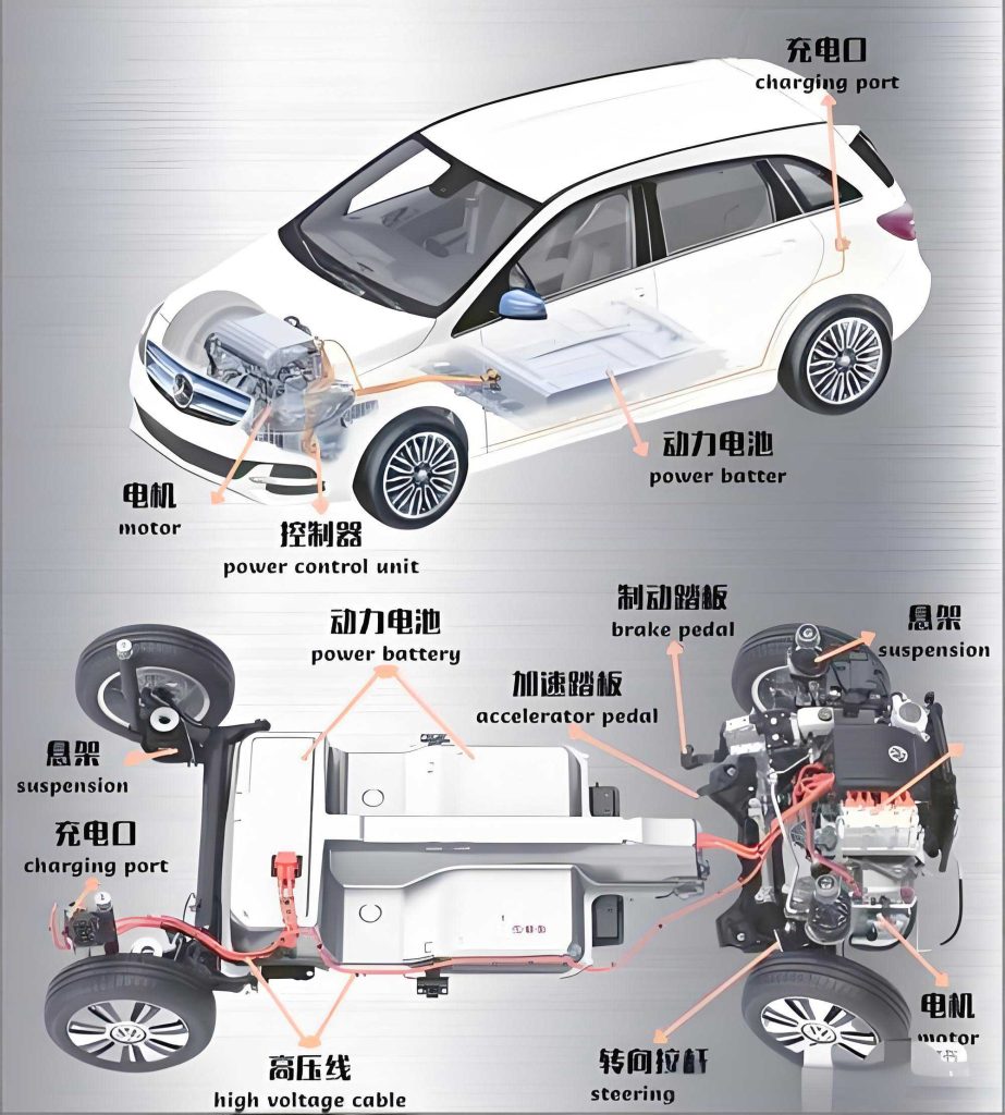
The high-voltage generator is a core component of the range-extender system in battery electric cars, directly coupled to the engine via splines. It integrates a generator controller (GCU) with the generator body, converting AC to DC through PWM rectification to charge the battery and supply the drivetrain. In battery electric cars, these generators often operate on 400 V or 800 V platforms, subjecting them to harsh conditions like high temperatures, mechanical vibration, and frequent torque changes, which accelerate insulation aging. My investigation into a specific fault revealed that the battery electric car experienced a high-voltage power-up failure and limited power output, with the battery management system (BMS) reporting an initialization error. Initial insulation tests on the generator controller showed abnormal resistance: 0 Ω for the positive terminal to chassis and 40 kΩ for the negative terminal, far below the standard requirement of 20 MΩ. Further testing isolated the fault to the generator, as downstream components like the power distribution unit (PDU) and battery exhibited normal insulation.
The fault occurred during idle power generation in the range-extender, characterized by an abrupt torque drop and zero output from the GCU. To contextualize this, I referred to the national standard GB/T 18488—2024, which specifies insulation requirements for drive motor systems in battery electric cars. The key technical criteria are summarized in Table 1, outlining insulation resistance for stator windings and controller terminals under cold and hot states. The generator in question was designed with an H-class insulation grade, exceeding these standards as shown in Table 2 and Table 3. For instance, the design insulation resistance for windings to chassis was above 20 MΩ, with partial discharge inception voltage (PDIV) values over 956 V at 25°C and 803 V at 180°C. However, the fault indicated a severe deviation, necessitating a root-cause analysis.
| No. | Item | Condition | Technical Requirement |
|---|---|---|---|
| 1 | Stator winding to chassis insulation resistance | Cold state | >20 MΩ |
| 2 | Stator winding to chassis insulation resistance | Hot state | $$R \geq \frac{U_{dmax}}{1000} + \frac{P}{100} \text{, with } R_{min} \geq 0.38 \text{ MΩ}$$ |
| 3 | Stator winding to temperature sensor insulation resistance | Cold state | >20 MΩ |
| 4 | Stator winding to temperature sensor insulation resistance | Hot state | $$R \geq \frac{U_{dmax}}{1000} + \frac{P}{100} \text{, with } R_{min} \geq 0.38 \text{ MΩ}$$ |
| 5 | Controller insulation resistance (power terminals to chassis) | Cold state | ≥1 MΩ |
| 6 | Controller insulation resistance (power terminals to chassis) | Hot state | ≥1 MΩ |
| 7 | Controller insulation resistance (power terminals to signal terminals) | Cold state | ≥1 MΩ |
| 8 | Controller insulation resistance (power terminals to signal terminals) | Hot state | ≥1 MΩ |
Here, $U_{dmax}$ represents the maximum operating voltage in volts, and $P$ is the continuous power in kilowatts. For battery electric cars, these parameters are critical for ensuring safety and reliability.
| Component | Design Indicator |
|---|---|
| Flat copper wire | Insulation layer thickness ≥62 μm |
| Insulating varnish | PDIV > 956 V (25°C), PDIV > 803 V (180°C) |
| Insulation paper | H-class flame-retardant resin (drip varnish) |
| Insulation powder | Thermal class: H (180°C), breakdown strength >20 kV/0.5 mm (200°C, 500 h) |
| Insulation Test Item | Judgment Standard (MΩ) | Test Result (MΩ) |
|---|---|---|
| Winding to chassis insulation resistance | >20 | >2000 |
| Temperature sensor to chassis insulation resistance | >20 | >2000 |
| Resolver to chassis insulation resistance | >20 | >2000 |
| Coil to resolver insulation resistance | >20 | >2000 |
| Coil to temperature sensor insulation resistance | >20 | >2000 |
| Controller power terminals to chassis | >20 | 10150 |
Upon disassembling the faulty generator, I found that the U-phase current sensor was melted, with powder residue on the PCBA and a pungent odor. The controller alone passed insulation tests, but further checks revealed that all three-phase busbars to chassis insulation had failed. Water jacket leak tests were negative, ruling out coolant leakage. The current sensor meltdown was likely due to a ground short in the windings, causing a frequency surge to 10 kHz and inducing eddy currents. To systematically analyze the fault, I constructed a fault tree analysis (FTA) focusing on winding-to-winding shorts, winding-to-chassis breakdowns, and winding-to-core shorts. The stator windings were star-connected with parallel branches, and resistance measurements showed balanced phases around 36 mΩ, excluding inter-turn or phase-to-phase faults. However, tests indicated abnormal insulation between windings and the core after removing the housing.
I conducted insulation tests on 12 key points, as summarized in Table 4. The results confirmed that winding resistances were normal (e.g., U-W line resistance of 35.06 mΩ cold and 37.04 mΩ hot), but insulation to the core was below 30 MΩ, pinpointing a winding-to-core short. PDIV tests on the stator assembly revealed failure, with sparking at the V-phase connection near the central busbar. Visual inspection showed crushed insulation paper at slot 56 on the outlet side, where the I-Pin wire root was damaged. This aligned with simulations indicating that slots 56 and 57 had greater axial movement due to design constraints, leading to insulation paper compression during assembly.
| Test Point | Test Item | Test Resistance (MΩ) | Result |
|---|---|---|---|
| 1 | U→W line resistance (cold) | 35.06 | Qualified |
| 2 | V→W line resistance (cold) | 35.04 | Qualified |
| 3 | U→V line resistance (cold) | 35.03 | Qualified |
| 4 | U phase to chassis | 29.52 | Unqualified |
| 5 | V phase to chassis | 29.36 | Unqualified |
| 6 | W phase to chassis | 29.54 | Unqualified |
| 7 | U→W line resistance (hot) | 37.04 | Qualified |
| 8 | V→W line resistance (hot) | 37.02 | Qualified |
| 9 | U→V line resistance (hot) | 37.00 | Qualified |
| 10 | U phase to core | <30 | Unqualified |
| 11 | V phase to core | <30 | Unqualified |
| 12 | W phase to core | <30 | Unqualified |
The root cause was traced to process inconsistencies during winding insertion. The insertion end height measured 24 mm, below the design value of 30 mm, due to an insufficient槽深 in the pressing盘 and poor tooth fork alignment. This caused the copper wire R-angle to compress the insulation paper against the core yoke. During operation, dynamic wear between the wire enamel, insulation paper, and core led to breakdown. Simulations of the winding geometry, using 3D models, confirmed that slots 56 and 57 had higher axial mobility, with slot 56 experiencing the most severe compression. The relationship between compression force and insulation failure can be expressed as:
$$ F_c = k \cdot \Delta h \cdot A $$
where $F_c$ is the compression force, $k$ is the material stiffness constant, $\Delta h$ is the height deviation, and $A$ is the contact area. For battery electric cars, minimizing $\Delta h$ is crucial to prevent such faults.
To address this, I implemented design and process improvements. The winding end heights were optimized: insertion end to 27.5 mm and welding end to 34.5 mm, balancing copper loss, temperature rise, and efficiency. Insulation paper protrusion was controlled to $(2.5 \pm 0.5)$ mm from the core end to avoid interference with I-Pin bends. The formula for optimal end height considers trade-offs:
$$ H_{opt} = \sqrt{\frac{P_{cu} \cdot R_{th}}{k_T}} $$
where $H_{opt}$ is the optimal end height, $P_{cu}$ is copper loss, $R_{th}$ is thermal resistance, and $k_T$ is a design constant. For battery electric cars, this optimization enhances insulation durability without compromising performance.
Process-wise, I modified trial production by replacing nylon tooth forks with metal ones (5.09 mm opening to match the 5.10 mm slot width) and redesigning the insertion盘 with a depth of 23.5 mm and挖孔 in I-Pin areas. For mass production, I introduced automated steps: servo-controlled paper insertion with visual inspection, pressure-displacement sensing during winding insertion to ensure 27.5 mm height, and radial “insertion needle” tools during twisting to secure insulation paper. These steps are summarized in Table 5, highlighting key parameters for battery electric car applications.
| Process Stage | Improvement | Key Parameter | Impact on Insulation |
|---|---|---|---|
| Paper Insertion | Servo control with visual inspection | Paper height: $(2.5 \pm 0.5)$ mm | Prevents paper misalignment and crushing |
| Winding Insertion | Pressure-displacement sensor use | Insertion height: 27.5 mm | Reduces compression on insulation paper |
| Winding Twisting | Radial insertion needle tool | Tooth fork thickness: 4 mm | Secures paper during twisting to avoid cuts |
| Tooling Design | Metal tooth forks and optimized盘 | Slot opening: 5.09 mm,盘 depth: 23.5 mm | Ensures proper fit and limits axial movement |
The effectiveness of these measures was validated through rigorous testing. On the bench, the improved generator withstand a 1000 V application for 60 seconds, with insulation resistance above 20 MΩ for windings to chassis and sensors. It also passed a 1800 V power-frequency耐电压 test with leakage current below 10 mA, meeting the standard for battery electric cars. The insulation resistance after testing can be modeled as:
$$ R_{ins}(t) = R_0 \cdot e^{-\alpha t} + R_{\infty} $$
where $R_{ins}(t)$ is the insulation resistance over time, $R_0$ is initial resistance, $\alpha$ is the aging coefficient, and $R_{\infty}$ is the steady-state resistance. For the optimized design, $R_{\infty}$ remained high, indicating robust performance.
Vehicle-level testing involved installing the generator in a battery electric car for a 50,000-kilometer durability run. Under continuous and peak power conditions, the system performed flawlessly, with no insulation faults observed. Post-test disassembly confirmed normal insulation resistance, demonstrating the improvements’ reliability in real-world battery electric car environments. This aligns with the overarching goal of enhancing safety and longevity in battery electric cars.
In conclusion, my analysis of this insulation fault in a high-voltage generator for battery electric cars underscores the importance of integrated design and process control. By optimizing winding geometries, material selection, and manufacturing steps, I successfully mitigated winding-to-core shorts, a common issue in battery electric cars. The improvements were validated through both bench and整车 tests, ensuring compliance with insulation standards. This case study highlights that for battery electric cars, proactive insulation management is essential to overcome operational challenges and advance electric vehicle reliability. Future work could explore advanced insulation materials or real-time monitoring systems to further bolster performance in battery electric cars.