
As an experienced technician in the field of new energy vehicles (NEVs), I have witnessed the rapid evolution of the electric drive system, the very heart of these vehicles. My daily work revolves around ensuring these complex systems operate reliably. The electric drive system, integrating the motor, controller, and transmission, is fundamental to vehicle performance, efficiency, and safety. Its failure directly impacts the driver’s experience and safety. Therefore, a deep, systematic understanding of its fault mechanisms and the mastery of precise maintenance procedures are paramount. This guide consolidates my practical experience and technical knowledge into a detailed framework for diagnosing and repairing the modern automotive electric drive system.
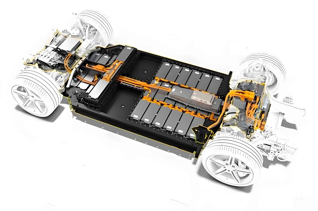
The electric drive system is a sophisticated assembly. Its primary components include the traction motor, which converts electrical energy into torque; the power electronics controller (inverter), which manages power flow from the battery to the motor; the reduction gearbox and differential, which adjust torque and speed; and a network of sensors and wiring harnesses that provide critical feedback for control. A holistic view of this system is essential for effective troubleshooting.
Diagnosing faults in the electric drive system requires a methodical approach. It always begins with ensuring high-voltage safety—verifying the system is powered down and properly isolated. The onboard diagnostic (OBD) system is the first port of call, providing fault codes that point to specific subsystems. However, codes are only starting points. Effective diagnosis combines data from scan tools with physical inspections, electrical measurements, and functional tests to pinpoint the root cause within the intricate electric drive system.
Common Fault Types and Root Causes in the Electric Drive System
Failures within the electric drive system can be categorized by their originating component. Each category presents distinct symptoms and underlying causes, which are summarized in the table below.
| Subsystem | Component | Common Fault Symptoms | Primary Root Causes |
|---|---|---|---|
| Traction Motor | Stator Windings | Loss of power, excessive heat, abnormal noise, insulation warning. | Overheating, voltage spikes, moisture ingress, manufacturing defects. |
| Rotor (Permanent Magnet) | Reduced torque, loss of efficiency, irregular vibration. | High-temperature demagnetization, mechanical impact, corrosion. | |
| Bearings | High-pitched whining or grinding noise, vibration, overheating. | Lubrication failure, contamination, improper installation, fatigue. | |
| Cooling System | Motor overheating, thermal derating, performance loss. | Coolant leaks, pump failure, blocked coolant channels, fan malfunction. | |
| Motor Controller | Power Modules (IGBTs/MOSFETs) | Complete loss of drive, “check engine” light, controller overheating. | Overcurrent, overvoltage, short circuits, thermal cycling fatigue. |
| DC-Link Capacitors | Reduced performance, voltage instability, controller errors. | Aging, high ESR (Equivalent Series Resistance), voltage stress. | |
| Control Board | Erratic motor behavior, communication faults, no power. | Corrosion, vibration-induced solder cracks, component failure. | |
| Transmission | Reduction Gears / Differential | Whining, howling, or clunking noises, vibration, fluid leaks. | Insufficient lubrication, gear wear/pitting, bearing failure, misalignment. |
| Shafts & Seals | Oil leaks, contamination ingress, noise. | Seal hardening/cracking, shaft wear or damage. | |
| Sensors & Wiring | Position/Speed/Temp Sensors | Erratic torque delivery, system shutdown, implausible signal errors. | Sensor damage, magnetic debris interference, wiring issues. |
| High-Voltage Wiring | Intermittent faults, insulation warnings, catastrophic short circuits. | Insulation abrasion, connector corrosion/pitting, thermal degradation. |
Advanced Diagnostic and Maintenance Procedures
Traction Motor Maintenance Protocol
My approach to motor repair is sequential. After safe high-voltage isolation, I perform a visual inspection for physical damage, coolant traces, or burnt odors. Electrical integrity is checked next. For three-phase AC motors, winding resistance is measured between each phase terminal. The resistances should be balanced within a few percent. A significant deviation indicates a short or open circuit. $$ R_{U-V} \approx R_{V-W} \approx R_{W-U} $$ Insulation resistance ($R_i$) is critical for safety and is tested using a megohmmeter, applying a high DC voltage (e.g., 500V or 1000V) between the windings and the motor casing. The acceptable minimum is typically >100 MΩ. The calculation is straightforward: $$ R_i = \frac{U_{test}}{I_{leakage}} $$ where $U_{test}$ is the applied test voltage and $I_{leakage}$ is the measured leakage current.
For bearing replacement, precise mechanical work is key. After disassembly, the bearing housing is meticulously cleaned. The new bearing must be heated uniformly for installation—never hammered—to avoid damaging the races. The correct lubrication type and quantity, as specified by the manufacturer, are crucial for longevity. Post-repair, I conduct a no-load test, gradually increasing speed while monitoring current draw and vibration, before proceeding to a loaded dynamometer test to verify torque output against specifications.
Motor Controller Repair and Insulation Analysis
The controller is the most electronics-intensive part of the electric drive system. Diagnosis starts with OBD codes and a thermal inspection for hotspots. Internal inspection focuses on the power module and DC-link capacitors. I use a multimeter in diode-test mode to check each IGBT’s freewheeling diode. A shorted or open diode indicates a failed transistor. Capacitors are checked for bulging tops or leaking electrolyte; their Equivalent Series Resistance (ESR) can be measured with a specialized meter—a high ESR value renders a capacitor ineffective at filtering.
Insulation testing of the controller itself is non-negotiable. The procedure involves testing between all high-voltage terminals (DC+, DC-, AC phases) and the controller’s grounded heat sink/chassis. Using the formula above, the measured insulation resistance must exceed a strict threshold, often 1 MΩ per volt of operating voltage or a minimum of 10-20 MΩ. For a 400V system, a test voltage of 600V DC is applied. If $R_i$ is below spec, it indicates internal contamination, damaged insulation, or tracking on the PCB, necessitating detailed cleaning or board replacement.
Controller software and calibration are often overlooked. After hardware repair, flashing the latest firmware and verifying calibration parameters (like phase current sensor offsets) are essential final steps to ensure the controller operates correctly within the broader electric drive system.
Transmission System Overhaul
Transmission faults in an electric drive system are predominantly mechanical. The diagnostic sequence involves noise localization under different load conditions (acceleration, deceleration, coasting). Gear wear patterns tell a story: pitting indicates fatigue, while scoring suggests lubrication issues. Clearances are paramount. The backlash between gears and the preload on differential bearings must be measured with dial indicators and adjusted using selective shims to precise micron-level tolerances specified in the service manual.
The lubrication equation is vital for preventative maintenance. The correct oil viscosity ($\eta$) and additive package are selected based on the specific gear geometry and expected operating shear rate ($\dot{\gamma}$). The shear stress ($\tau$) within the gear contact is approximated by: $$ \tau \approx \eta \cdot \dot{\gamma} $$ Using an oil with too low a viscosity leads to increased metal-to-metal contact and wear, while oil that is too viscous causes excessive churning losses and overheating. Post-overhaul, a run-in procedure with gradual load increase is followed to ensure proper mating of new components.
Sensor and Wiring Harness Diagnostics
Sensor faults can mimic more severe component failures. My process is to compare the sensor signal to a known-good value or to another correlated signal. For example, the resolver (motor position sensor) outputs sinusoidal signals. Their amplitude and phase relationship must be perfect. Imbalance indicates a faulty resolver. I use an oscilloscope to view these waveforms directly.
For wiring, continuity tests are basic. More advanced is checking for “intermittent opens” or high-resistance connections by performing a voltage drop test under load. A voltage drop of more than 0.1V across a connector or section of wire while the system is operating suggests a problematic connection. For high-voltage cables, Partial Discharge (PD) testing is the gold standard for detecting microscopic insulation weaknesses before they cause a full breakdown. This non-destructive test applies an AC voltage and detects the high-frequency emissions from small internal discharges.
Synthesis and Proactive Maintenance Philosophy
Effective maintenance of the electric drive system is not merely reactive; it is increasingly predictive and data-driven. By logging operational parameters like peak temperatures, torque ripple spectra, and insulation resistance trends over time, one can forecast potential failures. The integration of diagnostic data, precise measurement, and adherence to rigorous procedures forms the cornerstone of reliable electric drive system service. Ultimately, understanding the interconnectedness of all subsystems—how a failing cooling sensor can lead to controller over-temperature shutdown, or how gearbox wear debris can contaminate a motor’s resolver—is what separates competent repair from expert diagnostics. This systemic, first-principles approach ensures the longevity and safety of the vehicle’s most critical powertrain component.