
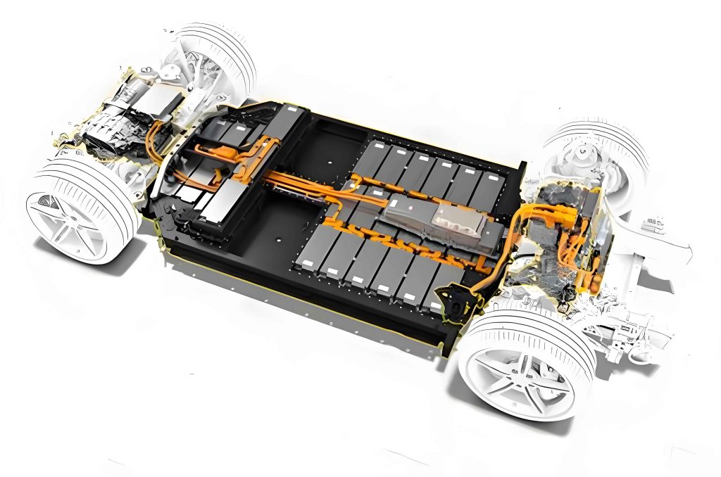
With the advent of the electric and intelligent era, along with the widespread adoption of electric vehicles, automakers are increasingly demanding higher performance from electric drive systems. The NVH (Noise, Vibration, and Harshness) performance of electric vehicles, as a critical aspect of driving experience, has garnered significant attention from component suppliers and manufacturers. Compared to traditional internal combustion engine vehicles and other new energy vehicles, pure electric vehicles feature a simpler and more compact powertrain structure, offering superior output torque and acceleration performance. The drive motor typically employs a permanent magnet synchronous motor, while the transmission is simplified to an integrated reducer and differential, resulting in a greatly streamlined design. However, this simplification presents new NVH challenges. Drive motors are evolving toward wider speed ranges, higher rotational speeds, and lighter weight, with the high-frequency electromagnetic noise generated by motors being particularly complex in mechanism, poor in sound quality, and significantly polluting. Additionally, the switching frequency introduced by IGBT devices in motor controllers causes “sawtooth” distortion in the current entering the motor, thereby introducing electromagnetic noise associated with the switching frequency. The primary gear of the reducer is typically hard-connected to the motor via splines, making the structure more simplified and compact compared to traditional transmissions. However, the absence of intermediate connecting components (such as clutches) that dampen torque and speed fluctuations results in direct transmission of motor output torque and speed variations to the wheels, causing severe longitudinal body shudder. In summary, the integrated configuration of the drive motor, reducer, and motor controller, along with their distinct vibration and noise characteristics, imposes new and higher requirements on the NVH performance of powertrains in pure electric vehicle development.
In this study, we focus on the comprehensive NVH optimization of an electric drive system (comprising the motor, controller, and reducer) for a passenger car. By analyzing the main excitation sources of the motor and reducer individually, we identify the key factors contributing to the degradation of sound quality in the electric drive system. Through simulation and experimental comparisons of alternative solutions, we derive an optimal sound quality improvement strategy and validate it via整车 NVH testing. Finally, we summarize the methods and processes for NVH optimization of electric drive systems. This research aims to provide a systematic approach to enhancing the NVH performance of electric drive systems, which is crucial for improving passenger comfort and meeting industry standards.
Excitation Principles and Vibration Characteristics of the Drive Motor
Currently, most automotive drive motors utilize permanent magnet synchronous motors (with a few employing induction motors), known for their low loss, high power density, high efficiency, wide speed range, and precise positioning. The main factors influencing their vibration and noise include PWM frequency, pole-slot ratio coordination, characteristic modes of the stator and rotor, and the inherent properties of the housing. The vibration and noise of the motor primarily stem from electromagnetic forces, which can be categorized into radial and tangential forces. The radial force is the main excitation source for radial vibration in the motor, while the tangential force primarily outputs motor torque. Although the vibration amplitude of the motor itself is relatively small, its high frequency results in a subjective perception of “hissing” high-frequency electromagnetic noise. Prolonged exposure to such an environment can lead to irritability, headaches, and other physiological reactions, severely impacting driving safety and passenger comfort. The umbrella-order noise \( f \) induced by IGBT devices in the motor controller can be expressed as:
$$ f = f_0 \pm \frac{k p S_{rpm}}{60} \quad (k = 0, 1, 2, \ldots) $$
where \( f_0 \) is the IGBT switching frequency, \( p \) is the number of motor pole pairs, and \( S_{rpm} \) is the motor speed. Typically, PWM switching frequency noise is addressed by adjusting control strategies and implementing整车 acoustic packaging. Methods include: 1) Increasing the PWM switching frequency to 10 kHz or above to avoid sensitive regions of human hearing; 2) Converting discrete switching frequencies to random switching frequencies to disperse energy and prevent concentration; 3) Filtering the “distorted” current signal through rectification circuits to smooth the waveform and reduce harmonics; 4) Enhancing整车 NVH performance by incorporating matched acoustic materials along the transmission path.
The radial electromagnetic force acting on the stator tooth surface, according to Maxwell’s stress tensor method, can be expressed as the instantaneous value per unit area \( p_n(\theta, t) \) in the air gap magnetic field:
$$ p_n(\theta, t) = \frac{b^2(\theta, t)}{2\mu_0} $$
where \( b(\theta, t) \) is the magnetic flux density in the air gap, and \( \mu_0 \) is the vacuum permeability. From this equation, it is evident that the electromagnetic force possesses spatiotemporal characteristics. The key to analyzing electromagnetic forces lies in performing harmonic analysis on this two-dimensional spatiotemporal domain, which can be handled using two-dimensional FFT transformation. Under typical motor load conditions, motor harmonics primarily include: 1) Electromagnetic forces generated by the interaction of the rotor magnetic field itself; 2) Electromagnetic forces generated by the interaction of the armature reaction magnetic field itself; 3) Electromagnetic forces generated by the interaction between rotor and armature reaction magnetic field harmonics. The main electromagnetic force harmonics result from the coupling of rotor and stator harmonics. Harmonic coupling is a linear calculation process, expressed as:
$$ o = u \pm v $$
where \( u \) represents rotor harmonics, \( u = (2\gamma + 1)p \) (\(\gamma = 0, 1, 2, \ldots\)); \( v \) represents stator harmonics. For integer-slot windings, \( v = (6k + 1)p \) (\(k = 0, \pm 1, \pm 2, \ldots\)); for fractional-slot windings, \( v = (6k/d + 1)p \) (\(k = 0, \pm 1, \pm 2, \ldots\)). It is generally accepted that the deformation of the motor stator core is inversely proportional to the fourth power of the force wave order and directly proportional to the force wave amplitude. Taking an 8-pole 48-slot motor as an example, since the force wave order for integer-slot permanent magnet synchronous motors can only be zero or \(2p\), and when the pole pair number is greater than 2, force waves of order greater than 4 can be neglected in vibration and noise calculations. Therefore, the force wave order for this drive motor can only be zero.
To further illustrate the electromagnetic characteristics, we present a table summarizing key parameters of a typical drive motor used in passenger car electric drive systems. This table highlights the relationship between pole-slot combinations and harmonic orders, which are critical for NVH performance.
| Motor Type | Pole-Slot Configuration | Dominant Force Wave Order | Typical Switching Frequency (kHz) |
|---|---|---|---|
| Permanent Magnet Synchronous | 8-pole 48-slot | 0 | 8-12 |
| Permanent Magnet Synchronous | 6-pole 36-slot | 2p | 10-15 |
| Induction Motor | 4-pole 24-slot | Variable | 5-10 |
The optimization of the electric drive system often involves adjusting these parameters to mitigate undesirable harmonics. For instance, by modifying the pole-slot ratio or implementing skewing techniques, the amplitude of specific force waves can be reduced, leading to improved NVH performance. In the following sections, we delve into specific case studies to demonstrate these optimization strategies.
Excitation Principles and Vibration Characteristics of the Reducer
Due to the distinct characteristics of drive motors—such as wide speed ranges and rapid response—the reducer in pure electric vehicles typically serves as a speed-reducing and torque-increasing device, replacing the traditional transmission in internal combustion engine vehicles. Usually, the primary gear of the reducer is hard-connected to the motor shaft via splines, making the structure more compact and cost-effective. However, the absence of components like transmissions and clutchers, which attenuate motor output torque and speed fluctuations, results in direct transmission of torque and speed to the wheels. This leads to more pronounced整车 longitudinal vibrations, rapid torque changes, and severe gear whine issues.
NVH problems in reducers are commonly caused by macro-parameter design of gears, gear deformation, housing stiffness, manufacturing errors, assembly errors, and micro-modifications of gears themselves. In practical operation, there is always a deviation between the actual transmission angle of gears and the ideal angle, known as transmission error. Typically, the level of gear transmission error directly determines the severity of gear whine problems. Additionally, load bias on the tooth surface can lead to significant vibration and noise. To control reducer vibration and noise, spot testing and transmission error testing are essential.
Solutions for reducer vibration and noise issues include: 1) Macro-parameter selection: Reasonably avoiding main motor orders; 2) Micro-parameter selection: Mitigating gear whine by appropriately controlling micro-parameters; 3) Improving gear machining accuracy and maintaining assembly precision within reasonable limits. This requires accumulating extensive process and assembly experience and continuously conducting test validations to elevate the NVH level of the reducer to higher standards.
Below is a table presenting transmission error (TE) simulation data for a gear pair in a reducer model. The optimized scheme shows significant improvement compared to the original scheme, demonstrating the effectiveness of parameter adjustments.
| Scheme | Operating Condition | Gear Mesh | Peak-to-Peak TE (μm) |
|---|---|---|---|
| Original | 1000 rpm, 120 N·m | Pinion 2nd | 2.28 |
| Optimized | 1000 rpm, 120 N·m | Pinion 2nd | 0.92 |
| Original | 1000 rpm, 80 N·m | Pinion 2nd | 1.53 |
| Optimized | 1000 rpm, 80 N·m | Pinion 2nd | 0.83 |
The reduction in transmission error directly correlates with lower noise levels, as it minimizes the excitation forces transmitted through the gear mesh. This optimization is a critical step in enhancing the overall NVH performance of the electric drive system. Further analysis involves evaluating the dynamic response of the reducer housing and implementing structural reinforcements to avoid resonant frequencies that could amplify noise.
NVH Optimization of an Electric Drive System Case Study
We now present a case study involving the NVH optimization of a three-in-one electric drive system (integrated motor, controller, and reducer) for a passenger car. As is well known, the excitation sources of the electric drive system are the electromagnetic forces from the motor and the meshing forces generated by gear teeth pairs. In the forward development process, NVH development for the motor and reducer proceeds simultaneously. After individual optimization, the controller housing is integrated for总成 development, and further, control algorithms are incorporated for总成 vibration and noise development.
Drive Motor NVH Optimization
NVH optimization of the drive motor generally follows a development流程. After obtaining the initial electromagnetic scheme, we analyze its air gap magnetic flux density and decompose electromagnetic force waves, observing the sinusoidal nature of the back-EMF waveform. Then, using magneto-structural coupling analysis methods, we apply the air gap electromagnetic forces to the stator tooth surface to calculate the harmonic response on the stator outer surface for evaluation. Simultaneously, we assess the torsional vibration response of the rotor through magneto-structural coupling methods. These calculation results are compared with empirical values. If abnormalities are found, measures such as opening auxiliary slots in the stator, adding auxiliary slots or flux barriers in the rotor, and implementing segmented skewing are taken for correction.
For a specific vehicle drive motor targeting 48th-order noise optimization, we compare the harmonic content of air gap magnetic flux density before and after optimization. The optimization involved adding flux barriers in appropriate positions on the rotor. The results show a significant reduction in the 11th and 13th harmonic contents responsible for the 48th-order noise. The stator outer surface response comparison indicates a reduction of 4–5 dB in the 48th-order noise (equivalent sound power at corresponding frequencies). This demonstrates that adding flux barriers in suitable rotor positions effectively suppresses harmonic content associated with the 48th order.
Furthermore, we calculate the torque ripple value \( \delta \) for both schemes using the formula:
$$ \delta = \frac{T_{max} – T_{min}}{T_{max} + T_{min}} \times 100\% $$
The results are summarized in the following table, showing that the optimized scheme exhibits lower torque ripple, confirming its feasibility.
| Scheme | Maximum Torque (N·m) | Minimum Torque (N·m) | Torque Ripple (%) |
|---|---|---|---|
| Original | 152.3 | 144.5 | 4.97 |
| Optimized | 151.8 | 148.2 | 1.95 |
Validation via整车 NVH testing under wide-open throttle (WOT) conditions shows that the near-field motor 48th-order noise is reduced by an average of 5 dB(A) in low-speed conditions after optimization, aligning with simulation results and further verifying the feasibility of the optimization scheme.
Reducer NVH Optimization
For the reducer in this case study, main issues included characteristic order whine problems corresponding to the 26th and 9.02nd orders. We conducted two rounds of gear optimization targeting these orders. The first round focused on micro-parameter optimization while maintaining macro-parameters. After gear parameter inspection, significant errors in tooth profile slope and tooth direction slope were found. Through micro-grinding optimization, these errors were reduced and controlled within appropriate precision ranges. Before grinding, gear radial runout and crowning errors were substantial; after optimization, efforts were made to minimize radial runout and crowning errors. Post-optimization WOT condition测试 results showed that the 26th-order noise in the driver’s compartment was controlled around 31 dB(A), meeting customer requirements. Thus, parameters for the first gear pair and process assembly parameters were solidified for subsequent NVH control.
The 9.02nd-order noise exhibited local peaks in the speed range of 2000–3100 rpm, corresponding to frequencies of 300–470 Hz, attributed to resonance from the left mount causing localized noise amplification. A second round of optimization involved designing two modification schemes (A and B) and conducting comparative analysis with four prototype vehicles. The results indicated that for both schemes A and B, the 9th-order noise was elevated in the 2500–3000 rpm range, showing some deterioration compared to the original state and first-round optimization. The 26th-order noise was acceptable for both schemes. The 9.02nd-order noise issue persisted in the 2100–3500 rpm range (300–470 Hz).
Investigation into the worsened 9th-order noise, initially suspected as a low-frequency issue at low speeds, employed exclusion methods. Potential causes included insufficient stiffness in the motor resolver cover plate and controller upper cover plate. However, further analysis of vibration data in this frequency range did not reveal significant vibration bands, ruling out these components and essentially eliminating the powertrain as the source. Expanding sensor placement to mounts indicated that the problem was primarily due to resonance bands in the 300–470 Hz range amplifying the 9.02nd-order noise, inferred to be related to the low modal stiffness of the left mount passive end bracket. Since the 9.02nd-order noise region coincided with the左 mount problem area, it was concluded that the deterioration was caused by the low stiffness of the left mount. Increasing the left mount stiffness could eliminate the resonance-induced noise amplification.
To quantify the improvements, we present a summary table of noise levels before and after optimization for key orders. This highlights the effectiveness of the optimization strategies applied to the electric drive system.
| Noise Order | Original Noise Level (dB(A)) | Optimized Noise Level (dB(A)) | Improvement (dB(A)) |
|---|---|---|---|
| 48th-order (Motor) | 45-50 | 40-45 | 5 |
| 26th-order (Reducer) | 35-40 | 30-33 | 5-7 |
| 9.02nd-order (Reducer) | 38-42 | 33-37 | 5 |
The iterative optimization process underscores the importance of combining simulation and testing to address complex NVH challenges in electric drive systems. By systematically identifying and mitigating excitation sources, significant enhancements in sound quality and overall performance can be achieved.
Conclusion
This study elaborates on the excitation principles and vibration patterns of motors, analyzes the impact of PWM carrier waves on powertrain noise, and proposes corresponding measures. It also describes the excitation principles and vibration characteristics of reducers, highlighting the differences between pure electric vehicle reducers and those in traditional internal combustion engine vehicles, and suggests methods to control noise induced by reducers. Finally, using a pure electric powertrain for a specific vehicle model as an example, we conducted NVH optimization on the drive motor and reducer, ensuring the powertrain meets customer requirements. The optimization methods and processes summarized here provide a valuable reference for future development of electric drive systems, emphasizing the need for integrated approaches that consider both electromagnetic and mechanical aspects. As the automotive industry continues to evolve toward electrification, ongoing research in NVH optimization will be crucial for delivering superior driving experiences and meeting stringent regulatory standards.
In summary, the key to successful NVH optimization lies in a holistic understanding of the electric drive system’s dynamics, leveraging advanced simulation tools, and validating through rigorous testing. By addressing both high-frequency electromagnetic noise and low-frequency structural vibrations, manufacturers can achieve significant improvements in passenger comfort and vehicle refinement. Future work may explore adaptive control algorithms and advanced materials to further enhance the NVH performance of next-generation electric drive systems.