
As a researcher in the field of automotive engineering, I have observed the rapid evolution of intelligent connected vehicles (ICVs), which integrate advanced information technologies, data communication, and global positioning systems to enable smart interactions between vehicles, infrastructure, and humans. Electric control technology is a cornerstone of this transformation, particularly through components like the motor control unit, which plays a pivotal role in achieving autonomous driving. In this article, I will delve into the key components of ICV electric control technology, its specific applications in autonomous driving systems, and the associated challenges and countermeasures, all while emphasizing the criticality of the motor control unit. To enhance clarity, I will incorporate tables and mathematical formulas to summarize concepts, ensuring a comprehensive discussion that exceeds 8000 tokens in depth.
The electric control technology in ICVs is fundamentally composed of three core elements: sensors, control systems, and communication systems. Each component relies heavily on precise electronic management, where the motor control unit often serves as a central executor for vehicle functions. Below, I outline these components with detailed explanations and illustrative tools.
Sensors are the eyes and ears of ICVs, providing real-time data on vehicle status and environmental conditions. They enable functions such as state monitoring, environmental perception, and support for autonomous driving. For instance, radar and lidar sensors detect objects, while GPS and IMU sensors aid in localization. The data from sensors is processed by control systems, which include the motor control unit for actuating movements. To summarize sensor types and their roles, I present Table 1.
| Sensor Type | Primary Function | Data Output |
|---|---|---|
| Radar | Distance measurement to objects | Range, velocity |
| Lidar | High-resolution 3D mapping | Point cloud data |
| Camera | Visual recognition of lanes, signs | Image frames |
| GPS/IMU | Position and orientation tracking | Coordinates, acceleration |
| Temperature Sensors | Monitor engine and environment | Temperature readings |
The control system is the brain of ICVs, integrating sensor inputs to manage vehicle operations. It consists of a central controller and various actuators, with the motor control unit being a key actuator for driving functions. The central controller processes data using algorithms, while actuators like the motor control unit execute commands. The relationship can be modeled mathematically. For example, the control output for vehicle motion is often derived from sensor data fusion. Consider a simplified control law for speed regulation:
$$ v_{target} = K_p \cdot e(t) + K_i \int e(t) dt + K_d \frac{de(t)}{dt} $$
where \( v_{target} \) is the target velocity, \( e(t) \) is the error between desired and actual speed, and \( K_p, K_i, K_d \) are PID coefficients tuned by the motor control unit. This formula highlights how the motor control unit adjusts propulsion based on feedback. In practice, the motor control unit interfaces with multiple subsystems, as shown in Table 2.
| Component | Role | Example Functions |
|---|---|---|
| Central Controller | Data processing and decision-making | Engine control, path planning |
| Motor Control Unit | Actuates electric motors for motion | Speed adjustment, torque management |
| Brake Controller | Manages braking systems | Emergency stops, regenerative braking |
| Steering Controller | Controls steering mechanisms | Lane keeping, turn execution |
Communication systems enable connectivity,分为车载通信系统 (in-vehicle) and 车间通信系统 (vehicle-to-everything, V2X). These systems facilitate data exchange for cooperative driving, with the motor control unit often receiving remote commands. For instance, vehicle-to-vehicle (V2V) communication allows coordination to avoid collisions, which the motor control unit implements by adjusting speed. The data flow can be represented as:
$$ \text{Data Rate} = \frac{\text{Total Bits Transmitted}}{\text{Time Interval}} $$
This metric is crucial for real-time control by the motor control unit. I will now explore how these components apply to autonomous driving systems, focusing on path planning, driving decision-making, and control execution.
In autonomous driving systems, electric control technology is leveraged for path planning, which involves determining optimal routes based on real-time data. The motor control unit plays a vital role in executing planned trajectories. Path planning algorithms, such as A* or Dijkstra’s, use sensor inputs to compute routes. For example, the cost function for route selection can be expressed as:
$$ C = \sum_{i=1}^{n} (w_d \cdot d_i + w_t \cdot t_i + w_s \cdot s_i) $$
where \( C \) is the total cost, \( d_i \) is distance, \( t_i \) is traffic delay, \( s_i \) is safety risk, and \( w_d, w_t, w_s \) are weights. The motor control unit then actuates the vehicle along the chosen path. Table 3 summarizes key aspects of path planning applications.
| Technique | Description | Motor Control Unit Action |
|---|---|---|
| Global Path Planning | Uses map data for long-term routes | Maintains steady speed and direction |
| Local Path Planning | Adjusts for obstacles in real-time | Executes sudden turns or stops |
| Cooperative Planning | V2X communication for group coordination | Synchronizes acceleration with other vehicles |
Driving decision-making relies on sensor fusion and AI algorithms to interpret the environment and make choices. The motor control unit is critical in translating decisions into actions. For instance, when a sensor detects an obstacle, the system may decide to brake or swerve. This decision process can be modeled as a probabilistic framework, such as a Bayesian network:
$$ P(A|B) = \frac{P(B|A) \cdot P(A)}{P(B)} $$
where \( P(A|B) \) is the probability of action \( A \) given sensor data \( B \). The motor control unit then executes the action with precision. In autonomous driving, decisions are continuous, requiring the motor control unit to constantly adjust parameters. To illustrate, consider a decision matrix for common scenarios (Table 4).
| Scenario | Sensor Input | Decision | Motor Control Unit Command |
|---|---|---|---|
| Obstacle ahead | Lidar detects object at 10m | Decelerate or change lane | Reduce torque output or steer |
| Traffic light red | Camera recognizes signal | Stop vehicle | Apply regenerative braking |
| Highway merging | V2V communication on gap | Accelerate to merge | Increase motor speed smoothly |
Control execution involves the direct manipulation of vehicle actuators, with the motor control unit being paramount for motion control. It ensures that decisions are physically implemented, such as accelerating, braking, or steering. The dynamics of vehicle control can be described using equations of motion. For example, the force exerted by the motor control unit to achieve acceleration is given by:
$$ F = m \cdot a = \tau \cdot \frac{1}{r} $$
where \( F \) is force, \( m \) is mass, \( a \) is acceleration, \( \tau \) is torque from the motor control unit, and \( r \) is wheel radius. This highlights how the motor control unit converts electrical signals into mechanical action. In practice, the motor control unit coordinates with other controllers, as shown in Figure 1, which depicts its integration in an autonomous system. Here, I insert the provided hyperlink to visualize the motor control unit’s role:
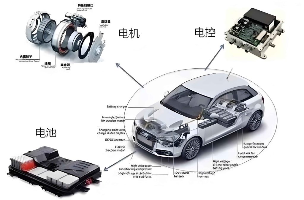
As seen in the image, the motor control unit is a compact electronic module that manages power delivery to motors, essential for autonomous functions. Its efficiency can be quantified using formulas like power loss calculation:
$$ P_{loss} = I^2 \cdot R $$
where \( I \) is current and \( R \) is resistance, emphasizing the need for optimized design in the motor control unit. Overall, the motor control unit’s reliability directly impacts system performance, making it a focal point in ICV development.
Despite advancements, applying electric control technology in autonomous systems faces several challenges. As a practitioner, I identify key issues and propose countermeasures, with the motor control unit often at the center of solutions.
One major challenge is data processing and parsing. Autonomous systems generate vast data streams from sensors, requiring real-time analysis for decisions. The motor control unit must process commands swiftly to avoid latency. For instance, if sensor data indicates a collision risk, the motor control unit needs to react within milliseconds. The complexity can be expressed as a computational load equation:
$$ \text{Load} = \sum_{i=1}^{n} \frac{\text{Data Size}_i}{\text{Processing Speed}_i} $$
where high loads can overwhelm the motor control unit. Another challenge is security. With increased connectivity, systems are vulnerable to hacking, which could compromise the motor control unit and lead to accidents. Ensuring encryption and secure communication is vital. Stability is also critical; any fault in the motor control unit might cause system failures. Lastly, regulatory gaps hinder deployment, as standards for motor control unit safety are still evolving. Table 5 outlines these challenges and potential countermeasures.
| Challenge | Description | Countermeasure | Role of Motor Control Unit |
|---|---|---|---|
| Data Processing | High-volume real-time data analysis | Use edge computing and AI algorithms | Integrate faster processors for quick response |
| Security Threats | Cybersecurity risks from hacking | Implement blockchain and intrusion detection | Include hardware security modules in design |
| System Stability | Reliability issues in complex environments | Redundant systems and fault-tolerant design | Employ backup motor control units for safety |
| Regulatory Hurdles | Lack of unified standards and laws | Collaborate with governments for frameworks | Adhere to emerging safety certifications |
To address these, I recommend strengthening technology fusion. For example, integrating cloud computing with the motor control unit can offload processing tasks. Additionally, investing in R&D is crucial for enhancing the motor control unit’s capabilities, such as improving its thermal management using formulas like heat dissipation:
$$ Q = h \cdot A \cdot \Delta T $$
where \( Q \) is heat transfer, \( h \) is coefficient, \( A \) is area, and \( \Delta T \) is temperature difference. Talent cultivation is also key; training engineers to specialize in motor control unit design will drive innovation. Finally, establishing comprehensive regulations will provide a safer ecosystem for deploying motor control unit-driven autonomous systems.
In conclusion, the application of electric control technology in intelligent connected vehicles is transformative for autonomous driving, with the motor control unit serving as a linchpin in execution. From sensor integration to control actuation, the motor control unit enables precise vehicle management. However, challenges like data complexity and security require ongoing research and collaboration. By leveraging tables and formulas, I have summarized key concepts, emphasizing the motor control unit’s role throughout. As the automotive industry evolves, continued focus on the motor control unit and its integration will be essential for achieving safe, efficient, and fully autonomous driving systems, ultimately contributing to societal advancements in transportation.