
In the context of global energy transition and increasing environmental awareness, new energy vehicles (NEVs) have emerged as a pivotal direction for the automotive industry due to their low emissions and high efficiency. As an automotive researcher and practitioner, I have observed that the electronic control system (ECS) serves as the core execution unit in NEVs, managing critical components such as the power battery and drive motor. Its high technical complexity and integration mean that any malfunction can lead to safety incidents. Given the diversity of faults in NEV ECS, traditional repair methods often fall short. Therefore, I believe an in-depth exploration of fault diagnosis and repair for these systems is essential to advance the NEV maintenance field and enhance vehicle safety and reliability.
The ECS in NEVs encompasses several key subsystems, including the battery management system (BMS), motor control unit (MCU), vehicle control unit (VCU), and charging control unit (CCU). In this article, I will analyze common fault types, diagnostic techniques, and repair strategies, emphasizing the role of the motor control unit. I will incorporate tables and formulas to summarize findings, aiming to provide a comprehensive guide for professionals. The increasing reliance on the motor control unit underscores the need for precise diagnostics and robust maintenance protocols.
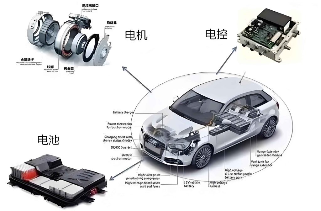
Common Fault Types and Causes in NEV Electronic Control Systems
From my experience, faults in NEV ECS can be categorized into four primary types, each with distinct causes. The motor control unit is particularly critical, as it directly influences propulsion performance. Below, I detail these faults and their origins.
Battery Management System Faults
BMS faults often manifest as voltage imbalance, abnormal charging/discharging, or temperature monitoring failures. I have identified three main causes: First, cell performance degradation—over time, individual cells exhibit varying capacity and internal resistance, leading to voltage disparities. This can be modeled using the voltage deviation formula: $$\Delta V = V_{\text{max}} – V_{\text{min}}$$ where $\Delta V$ represents the imbalance threshold. Second, sensor failures; BMS relies on voltage, current, and temperature sensors, and aging or damage can distort data. Third, wiring issues—vibration and high temperatures cause wear, short circuits, or poor contacts, disrupting signal transmission.
| Fault Cause | Typical Symptoms | Impact on System |
|---|---|---|
| Cell Degradation | Voltage imbalance, reduced range | Decreased battery efficiency |
| Sensor Malfunction | Inaccurate readings, false alarms | Compromised safety monitoring |
| Wiring Problems | Intermittent faults, data loss | System instability |
Motor Control Unit Faults
The motor control unit is a frequent source of issues, affecting power output. Common symptoms include startup failure, operational vibration, and weak acceleration. I attribute these to three factors: First, power device damage—insulated-gate bipolar transistors (IGBTs) in the motor control unit handle high currents and voltages, prone to breakdown from overcurrent, overvoltage, or poor散热. The power loss can be expressed as: $$P_{\text{loss}} = I^2 \times R_{\text{on}}$$ where $I$ is current and $R_{\text{on}}$ is on-state resistance. Second, control logic anomalies—software bugs or electromagnetic interference (EMI) distort control signals, disrupting motor operation. Third,散热 system failures; overheating triggers protection mechanisms, halting the motor control unit. I emphasize that the motor control unit’s reliability is paramount for NEV performance.
| Cause | Symptoms | Diagnostic Clue |
|---|---|---|
| IGBT Failure | No power output, burning smell | High current spikes in data流 |
| Software Error | Erratic speed control | Abnormal pulse-width modulation signals |
| 散热 Issue | Overheating shutdown | Temperature exceeding $$T_{\text{max}} = 85^\circ\text{C}$$ |
Vehicle Control Unit Faults
VCU faults, though less common, can be severe, causing vehicle immobility or component協調失调. I find three primary causes: First, core chip failure—prolonged operation leads to damage from voltage fluctuations or EMI. Second, software faults—bugs, failed updates, or malware cause logic混乱. Third, power supply issues—short circuits or unstable voltage prevent proper operation. The VCU orchestrates the entire ECS, so its health is crucial.
Charging Control Unit Faults
CCU faults result in charging failures, interruptions, or slow charging. I identify four causes: First, communication faults—poor connections or protocol mismatches with charging piles. Second, power module damage—rectifier/inverter modules fail under high load. Third, inadequate散热—overheating during charging. Fourth, wiring faults—short or open circuits. These issues directly affect user convenience and battery life.
Fault Diagnosis Technologies for NEV Electronic Control Systems
Effective diagnosis relies on multiple complementary techniques. I have applied these in practice and will discuss their principles and applications, with a focus on the motor control unit.
Fault Code Diagnosis Technology
This foundational method uses diagnostic tools to read fault codes from the ECS via the OBD interface. I often start with this approach, as it quickly narrows down fault ranges. For example, a code related to the motor control unit might indicate IGBT failure. However, intermittent faults may not generate codes, requiring additional methods.
Data Stream Analysis Technology
By reading real-time parameters, I compare them to standard ranges to identify anomalies. In the motor control unit, key parameters include motor speed, current, and temperature. The relationship can be described by: $$\tau = k_t \times I$$ where $\tau$ is torque and $k_t$ is torque constant. Deviations suggest sensor or control issues. I use this to pinpoint faults in the motor control unit’s feedback loops.
| Parameter | Normal Range | Fault Indicator |
|---|---|---|
| Motor Current | 0-200 A | Sustained >200 A suggests short circuit |
| Motor Temperature | 20-80°C | >80°C indicates散热 failure |
| PWM Duty Cycle | 0-100% | Erratic values point to control logic error |
Oscilloscope Detection Technology
I employ oscilloscopes to analyze signal waveforms in the ECS, especially for complex circuits in the motor control unit. For instance, the gate drive signal for IGBTs should have a clean square wave; distortion implies driver circuit faults. The voltage waveform can be expressed as: $$V(t) = V_{\text{dc}} + A \sin(2\pi f t)$$ where anomalies in amplitude $A$ or frequency $f$ indicate issues. This technique offers high precision for diagnosing the motor control unit’s electronic components.
Electromagnetic Compatibility Testing Technology
Given the sensitivity of the motor control unit to EMI, I use this technology to detect辐射 and susceptibility. It involves measuring electromagnetic fields and testing抗干扰能力. For example, if the motor control unit malfunctions under特定 conditions, shielding or grounding improvements may be needed. The interference threshold can be modeled as: $$I_{\text{EMI}} = \frac{P_{\text{rad}}}{d^2}$$ where $P_{\text{rad}}$ is辐射 power and $d$ is distance. This helps diagnose sporadic faults in the motor control unit.
Fault Repair Strategies for NEV Electronic Control Systems
Based on my findings, I propose targeted strategies to enhance repair efficiency and system longevity, continually referencing the motor control unit as a case study.
Targeted Repair Based on Fault Type
I advocate for customized approaches for each fault. For the motor control unit, if power devices are damaged, I replace IGBTs and inspect散热 systems. For control logic errors, I update software or patch vulnerabilities. The repair process for the motor control unit often involves recalibration using: $$\theta_{\text{校正}} = \theta_{\text{measured}} – \theta_{\text{offset}}$$ where $\theta$ represents motor angle. This ensures precise control restoration.
| Fault Type | Repair Action | Tool Required |
|---|---|---|
| Motor Control Unit IGBT Failure | Replace IGBT, test散热 | Soldering iron, thermal paste |
| Motor Control Unit Software Bug | Flash updated firmware | Diagnostic programmer |
| BMS Voltage Imbalance | Balance charge, replace cells | Balancer, multimeter |
Repair Process Optimization
I recommend a standardized five-step流程: fault reception, preliminary diagnosis, precise detection, repair implementation, and re-inspection. For the motor control unit, this includes verifying repairs through test drives and data流 checks. I document each step to build a knowledge base, improving future repairs of the motor control unit.
Technician Skill Enhancement
As ECS technology evolves, I stress the need for continuous training. Technicians should master motor control unit diagnostics through hands-on practice with simulators and real components. I propose regular workshops on advanced topics like waveform analysis and EMI mitigation for the motor control unit.
Preventive Maintenance and Full Lifecycle Management
I promote preventive measures to reduce faults, particularly in the motor control unit. This includes定期 inspections of散热, connections, and software updates. A lifecycle management system tracks usage data, predicting failures using models like: $$R(t) = e^{-\lambda t}$$ where $R(t)$ is reliability and $\lambda$ is failure rate. For the motor control unit, this can schedule part replacements before breakdowns occur.
Conclusion
In this article, I have explored the intricacies of fault diagnosis and repair for NEV electronic control systems. The motor control unit stands out as a critical component, requiring focused attention. By integrating diagnostic technologies such as data流 analysis and oscilloscope detection, and adopting targeted repair strategies, we can improve system reliability. I emphasize that ongoing innovation in diagnostics, especially for the motor control unit, is vital to support the NEV industry’s growth. Future research should delve into AI-driven fault prediction and adaptive control for the motor control unit, ensuring safer and more efficient vehicles.
My analysis demonstrates that a deep understanding of ECS principles, coupled with practical skills, enables effective maintenance. As NEVs become more prevalent, the role of the motor control unit will only expand, necessitating advanced tools and methodologies. I encourage professionals to embrace continuous learning and collaboration to advance this field, ultimately contributing to sustainable transportation solutions.