
Abstract In this paper, I delve into the internal resistance test methods for electric vehicles, aiming to enhance the efficiency of vehicle economy testing. I first analyze the sources of overall vehicle resistance, focusing on the impact of vehicle shape design on wind resistance. Key factors such as the air intake grille and chassis, as well as secondary factors like wheel arches and door handles, are discussed. I then propose a testing method using specialized equipment, which helps identify and resolve issues of excessive internal resistance by comparing developed models with benchmark models. The results demonstrate that the improved method effectively reduces energy consumption, thereby enhancing the economic and environmental performance of electric vehicles.
Keywords: electric vehicle; economy; vehicle resistance; internal resistance; efficiency
1. Introduction
The rapid development of the electric vehicle (EV) industry has made reducing energy consumption a shared goal in the automotive sector. Most 经济性 (economy) tests and validations for EVs are conducted on test benches, with vehicle resistance being a critical factor in early-stage testing. Vehicle resistance comprises three main components: wind resistance, tire rolling resistance, and internal resistance, which are typically measured through coasting tests on flat roads.
Internal resistance in electric vehicles refers to the resistance from driveline friction during road coasting tests. Its magnitude significantly impacts vehicle economy. Unstable internal resistance during the development phase can hinder economy testing, potentially rendering subsequent tests invalid. Therefore, establishing an effective method to detect and address abnormal internal resistance is crucial for improving EV efficiency and reducing energy waste.
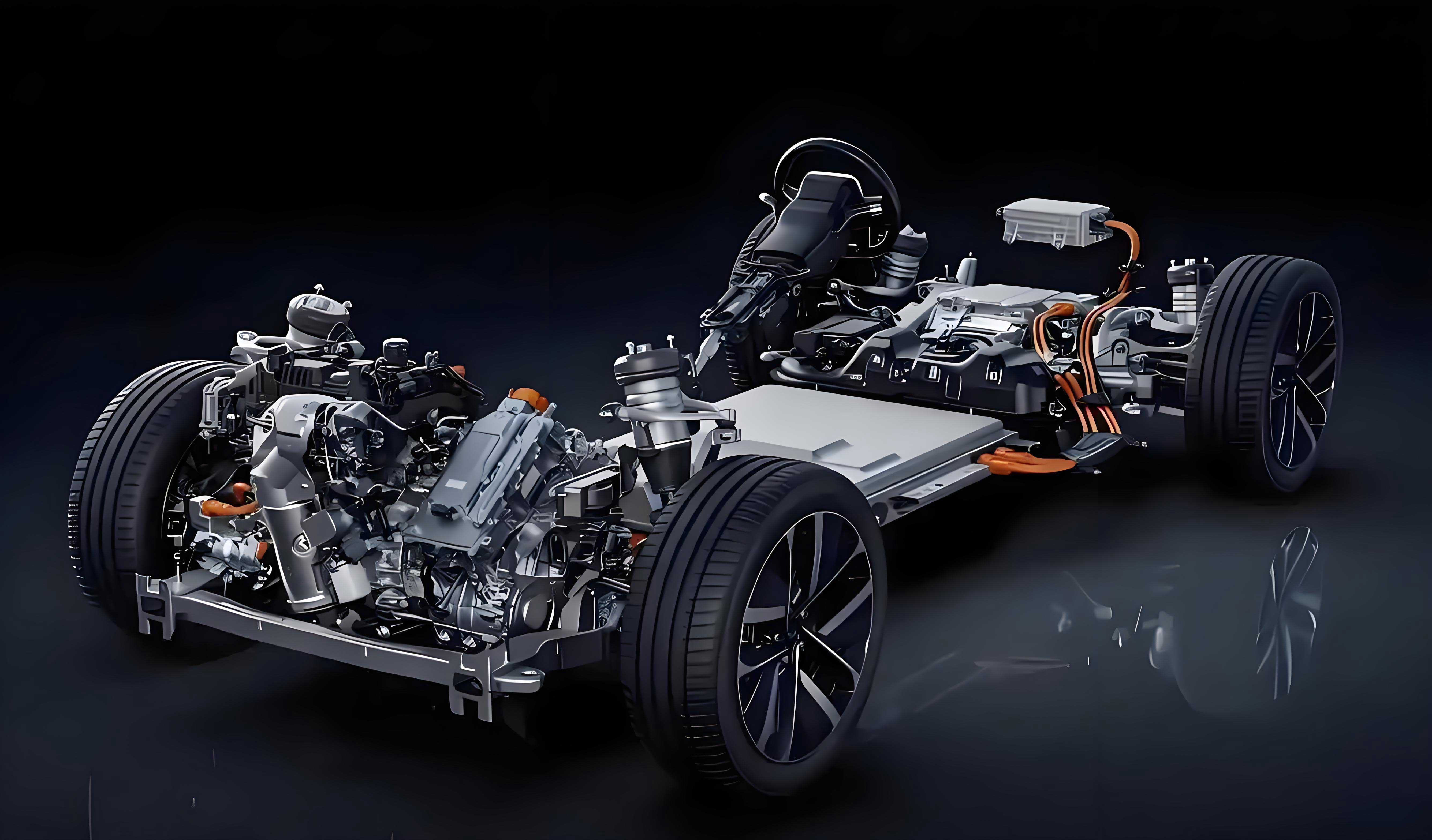
2. Decomposition of Vehicle Resistance
Vehicle resistance is divided into three primary categories: wind resistance, rolling resistance, and internal resistance. Each component influences energy consumption differently across varying speed ranges and operational conditions.
2.1 Wind Resistance
Wind resistance optimization plays a pivotal role in enhancing energy economy and driving stability for electric vehicles. Designers often adopt streamlined roofs and inclined windshields to reduce the air resistance coefficient (\(C_d\)). Additionally, minimizing body protrusions, optimizing wheel arches, and using low-drag side mirrors further reduce wind resistance.
The wind resistance formula is:\(D = \frac{1}{2} \times \rho \times V^2 \times A \times C_d\) Where:
- D = Air resistance (N)
- \(\rho\) = Air density (\(kg/m^3\))
- V = Vehicle speed (m/s)
- A = Frontal area (\(m^2\))
- \(C_d\) = Air resistance coefficient
Example: For a light commercial EV with \(C_d = 0.35\), \(A = 4.2~m^2\), and \(\rho = 1.204~kg/m^3\), the relationship between wind resistance and speed is significant. At speeds below 50 km/h, wind resistance remains under 200 N, minimally affecting energy consumption. However, above 80 km/h, it exceeds 400 N, significantly impacting efficiency (see Table 1 for comparative data on wind resistance coefficients of production EVs).
| Rank | Model | Wind Resistance Coefficient (\(C_d\)) |
|---|---|---|
| 1 | Mercedes-Benz EQS | 0.200 |
| 2 | Li Auto ET7 | 0.208 |
| 3 | Tesla Model 3 | 0.208 |
| 4 | Lucid Air | 0.210 |
| 5 | BYD Seal | 0.219 |
2.2 Rolling Resistance
Rolling resistance arises from tire-road interactions and internal tire friction. At speeds below 60 km/h, it dominates over wind resistance, while the opposite is true at higher speeds. The formula for rolling resistance is:\(F = k \times N\) Where:
- F = Rolling resistance (N)
- k = Rolling resistance coefficient
- N = Normal force (N)
Rolling resistance coefficients depend on tire construction, materials, and air pressure. Low-rolling-resistance tires reduce energy consumption but may compromise grip and wet-road performance. Table 2 compares rolling resistance and performance metrics across tire brands:
| Brand/Model | Tread Pattern | Speed Rating | Dry Braking (Score) | Dry Handling (Score) | Wet Braking (Score) |
|---|---|---|---|---|---|
| Michelin Primacy 4 | Symmetrical | 91W | 8.0 | 7.5 | 8.0 |
| Continental UC7 | Asymmetric | 91W | 8.0 | 8.0 | 8.5 |
| Chaoyang 11 | Linear | 91V | 8.0 | 7.0 | 7.0 |
| Pirelli CINTURATO P7 KS | Asymmetric | 91W | 7.0 | 7.5 | 6.0 |
2.3 Internal Resistance
Internal resistance, often overlooked despite its critical role, stems from driveline friction during coasting. It consists of three main components: motor drag torque, caliper drag torque, and hub bearing friction torque.
2.3.1 Motor Drag Torque
Motor drag torque arises from electromagnetic interactions within the motor. As the rotor spins, it induces an electromotive force in the stator, creating a resisting torque. The formula is:\(T_d = K \times \varphi \times I\) Where:
- \(T_d\) = Motor drag torque (N·m)
- K = Constant
- \(\varphi\) = Stator flux (Wb)
- I = Phase current (A)
This torque varies with motor speed, winding configuration, and rotor design, making it a dynamic component of internal resistance.
2.3.2 Caliper Drag Torque
Caliper drag torque occurs when brake pads partially remain in contact with discs after pedal release, causing residual friction. This torque is nearly constant and accounts for approximately 2% of total vehicle energy consumption. Proper caliper design and maintenance are essential to minimize this resistance.
2.3.3 Hub Bearing Friction Torque
Hub bearings support vehicle weight and handle radial/axial forces. Their friction torque is influenced by lubrication and load:\(M = M_0 + M_1\) Where:
- M = Total bearing friction torque (N·m)
- \(M_0\) = Lubrication-dependent torque (viscous losses)
- \(M_1\) = Load-dependent torque (mechanical friction)
At constant temperature, this torque is relatively stable and contributes about 2.5% to total energy loss.
3. Internal Resistance Testing Method
Accurate measurement of internal resistance is essential for optimizing EV efficiency. The following method utilizes specialized equipment to isolate and quantify each resistance component.
3.1 Testing Conditions
- Equipment: Vehicle torque testing devices, torque wrenches, and vehicle lifts to suspend wheels.
- Environment: Ambient temperature controlled between 5–30°C in a dry, stable setting.
3.2 Testing Procedure
- Preparatory Steps:
- Place the vehicle in neutral (N gear) and disable the parking brake.
- Lift the vehicle to ensure wheels are freely rotating and perform 10 pre-lubrication rotations.
- Measurement Steps:
- Connect testing equipment to each wheel and zero the device.
- Rotate each wheel at a constant speed (matching forward direction) for 3 cycles, recording torque values.
- For drive wheels, fix the opposite wheel and repeat measurements (see Table 3 for test setup details).
| Test Stage | Wheel Type | Measurement Action |
|---|---|---|
| Pre-test | All wheels | Rotate 10 times for lubrication |
| Main test | 从动轮 (Driven wheels) | Measure torque at constant speed |
| Main test | 驱动轮 (Drive wheels) | Fix opposite wheel, measure torque |
3.3 Data Processing
- Exclude startup torque data, recording only maximum torque during steady rotation.
- Calculate internal resistance:
- For driven wheels:\(F_{从动} = \frac{T_{总从动}}{R}\)
- For drive wheels:\(F_{驱动} = \frac{T_{驱动} + T_{固定对向}}{2R}\) Where:
- \(T_{总从动}\) = Total torque of driven wheels (N·m)
- \(T_{驱动}\) = Torque of drive wheels (N·m)
- \(T_{固定对向}\) = Torque of fixed opposite wheels (N·m)
- R = Wheel rolling radius (m)
3.4 Result Analysis
In a case study, a developed EV model exhibited higher resistance than a benchmark model during coasting tests. After excluding wind and rolling resistance, internal resistance testing revealed significant differences in both driven and drive wheels (Table 4).
| Wheel Position | Developed Model (N·m) | Benchmark Model (N·m) | Difference (N·m) |
|---|---|---|---|
| Front Left (Driven) | 3.6 | 0.7 | +2.9 |
| Front Right (Driven) | 2.2 | 1.0 | +1.2 |
| Rear Left (Drive) | 6.7 | 3.3 | +3.4 |
| Rear Right (Drive) | 2.9 | 2.0 | +0.9 |
The total internal resistance difference was 8.9 N·m, equivalent to 28.1 N of wheel-side resistance. Further investigation identified non-production-grade brake pads as the cause. Replacing them with design-compliant pads reduced internal resistance to benchmark levels, decreasing coasting resistance by 25.5 N and ensuring valid economy test results.
4. Optimization Strategies
To further reduce internal resistance, the following measures are recommended:
- Caliper Drag Torque: Adjust spring preload and piston clearance to minimize pad-disk contact.
- Hub Bearing Friction: Optimize seal designs and bearing interference fits to reduce mechanical losses.
- Motor Drag: Improve electromagnetic compatibility through gear and bearing design, and adjust motor load profiles to minimize idle resistance.
5. Conclusion
This study presents a practical method for testing internal resistance in electric vehicles, enabling effective energy consumption optimization. While the method’s simplicity may slightly compromise accuracy compared to complex bench tests, it offers efficiency by eliminating the need for large-scale equipment like four-motor test benches or roller dynamometers. By isolating and quantifying resistance components, this approach helps identify design flaws early in development, ensuring economy test validity and guiding EV energy-saving improvements. Future research should focus on refining test conditions to better simulate real-world driving scenarios, further enhancing measurement accuracy.