
During my years as a powertrain functional development engineer, I have learned that the transformation of an electric car from a concept to a mass-produced vehicle relies heavily on a rigorous functional strategy development process. Unlike an internal combustion engine vehicle, the electric car is propelled by discharging electrical energy stored in a traction battery pack. The entire journey from chemical energy to mechanical work at the wheels, and in the opposite direction during regenerative braking, is orchestrated by a complex set of functional strategies distributed among the battery management system, the drive motor controller, the vehicle controller and the thermal management controller. In this article, I share the methodology I use when developing these strategies and discuss the core functional domains that define safety, comfort, energy efficiency and reliability of an electric car.
Overview of an Electric Car Powertrain Architecture
Every electric car powertrain can be decomposed into a few major elements. The traction battery stores electrical energy; the electric drive system converts that energy into torque at the wheels; and the electronic control systems supervise the electrical conversion, the charging process and energy management. In my daily work I always start with an abstract architecture diagram, because the allocation of hardware controllers and the functional decomposition depend on where each capability physically resides.
More specifically, an electric car powertrain contains the following primary hardware modules:
- Traction battery – an energy storage container whose state is monitored by the BMS (Battery Management System).
- Electric drive unit – comprising an inverter and an electric machine. The inverter is commonly controlled by a DCU (Drive Control Unit), which may be integrated inside the inverter housing.
- Vehicle controller – the VCU (Vehicle Control Unit), which acts as the supervisor for torque arbitration, high-voltage sequence management and many electric-car-level functions.
- OBC (On-Board Charger) – the AC-to-DC converter responsible for converting grid AC power into DC power suitable for charging the battery.
- DC/DC converter – the high-voltage-to-low-voltage converter that charges the 12 V auxiliary battery and supplies the low-voltage loads.
- Thermal management system – the coolant circuits, refrigerant loops, electric water pumps, heaters and valves that maintain optimal temperatures for the battery, drive unit and power electronics.
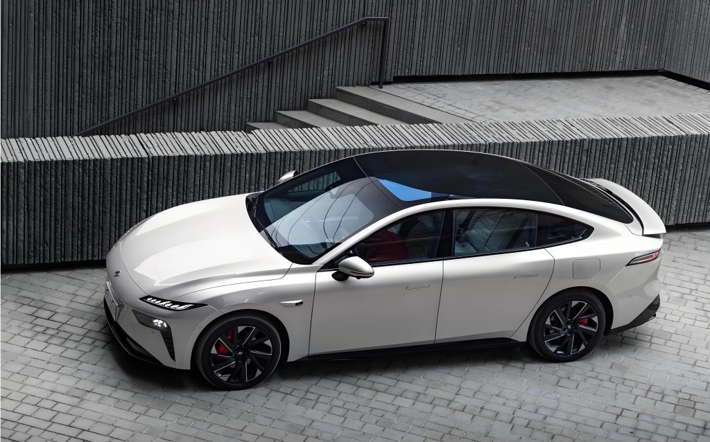
In the architecture I use as a baseline, the VCU communicates with the BMS and DCU over a controller area network. The BMS is responsible for measuring cell voltages, temperatures, pack current and insulation resistance, and for executing the closing and opening of the high-voltage relays. The DCU converts the VCU torque request into a sinusoidal phase current using pulse width modulation of high-power semiconductor switches. The OBC and the DC/DC converter are connected on the high-voltage DC bus and communicate with the VCU for enabling and de-rating decisions. From a functional perspective, the electric car powertrain is therefore not a chain of hardware pieces only; it is a distributed real-time system whose behavior is defined by the control strategies I develop and calibrate.
Constructing the Powertrain Functional List
In any electric car project, the starting point of functional development is a complete vehicle functional list. The list defines the functions that the end user experiences, including not only the obvious driving features but also charging, cabin pre-conditioning and safety responses. I have learned that a well-structured functional list becomes a binding contract between system engineers, software developers and calibration engineers. Without such a contract, derived requirements may become ambiguous and mismatched integration may appear late in the project.
The process I follow to create a functional list is divided into four iterative phases.
Requirement Collection
The first step is collection of requirements from market research, the sales portfolio, customer preferences, regulatory demands and competitive benchmarks. For an electric car, the most frequent customer complaints involve charging speed, winter range, torque smoothness, performance consistency and thermal-related degradation. I collect those complaints and translate them into functional topics that can be developed and verified.
Function Definition
Every collected requirement is transformed into a concrete functional item. I define each function with a clear name, a description, the application scenario and the implementation method. The function name should express the interaction among vehicle, system and component rather than merely naming a component. For example, “AC charging gun unlocking” is a function; “electric latch control” is a component description. The former is preferred in the functional list.
Function Hierarchical Decomposition
Functions are broken down into main functions, sub-functions and use cases (UCs). A main function corresponds to a major scenario from the user perspective, such as “charging management” or “driving experience”. Sub-functions address narrower scenarios, and each use case describes the exact input, judgment and output sequence. In my experience, use cases are the actual driver for software function implementation. A use case can be as simple as “when the gear selector is in D and the brake pedal is released, the vehicle remains stationary if the road is level” or as complex as “when the charging cable is inserted while the ignition is ON, the vehicle first enters the ready state and then automatically transitions to the charging state after shutting down the drive system”.
Review and Optimization
Multiple review cycles are always necessary. I invite system engineers from hardware, software, calibration, test and functional safety teams to review the list. Their combined feedback ensures completeness of normal operation, degraded operation and fault handling scenarios. The review is not a one-time event; it is a dynamic process that must adapt as new technologies and new user demands continuously reshape the electric car market.
To illustrate the hierarchical structure, Table 1 presents a portion of a powertrain-related functional list that I have used in a mid-size electric car project.
| Main function | Sub-function | Function description | Use-case examples |
|---|---|---|---|
| Charging management | Charging limit setting | Allow the user to set the charging cutoff SOC to reduce the number of full-charge cycles. | Smartphone app sets 80% SOC; infotainment screen sets 90%; departure charging schedule |
| AC charging gun unlocking | Allow the user to release the AC charging connector through multiple methods. | Smartphone APP unlock; automatic unlock after charging; key approach vehicle unlock; screen button unlock | |
| Driving experience | Driving mode switching | Adapt pedal response and energy recovery behavior to driver demand. | Eco mode; comfort mode; sport mode; individual mode; super-car mode |
| Reverse driving | Enable safe backward motion via negative torque. | R-gear selection while pressing brake; R-gear with speed less than 2 km/h | |
| High-voltage safety | Collision damage protection | Cut off high voltage in the event of a crash and illuminate the hazard lights. | Crash signal triggers high-voltage disconnect; hazard-lamp activation request |
Table 1 shows how the same “charging management” main function branches into different user scenarios. In a real electric car project, the number of such functions can exceed one hundred, and the number of use cases can reach several thousand. The functional list therefore becomes an essential traceability link for requirements, software code and test cases.
Detailed Functional Development of the Electric Car Powertrain
After the functional list and its use cases are approved, I move to detailed functional strategy development. In this section I summarize the six areas that I consider most critical for the electric car powertrain: high-voltage power-on/off control, tractive torque control, charging control, thermal management control, low-voltage energy management and fault-handling strategies.
High-Voltage Power-On and Power-Off Control
The word “high voltage” in an electric car usually means a battery voltage between 300 V and 900 V. Because direct connection of such a high voltage to a capacitive load produces very large inrush currents, the high-voltage power-on sequence is one of the most safety-critical functional areas. In my design, the VCU is responsible for arbitration of all power-on permissions. The VCU evaluates the driver’s request, the key or smart-entry states, high-voltage interlock loop, network communication status, requested vehicle mode and the presence of severe faults. If every condition is satisfied, the VCU sends an enabling request to the BMS; otherwise, it acknowledges the request and keeps the high-voltage bus disconnected.
For a normal key-start procedure, the following steps are typical:
- The driver presses the braking pedal and the start button.
- The VCU receives the start command, verifies that the transmission is in Park, the AC charging plug is disconnected and all controllers are awake.
- The VCU requests the BMS to close the negative main relay and the pre-charge relay.
- The current flows through the pre-charge resistor and begins to charge the DC-link capacitance in the inverter.
- When the bus voltage rises above a threshold, conventionally 90% to 95% of the battery open-circuit voltage, the BMS closes the positive main relay and opens the pre-charge relay.
- The high-voltage system is now in an active state and ready to provide torque and auxiliary power.
During the pre-charge phase, the bus voltage follows the well-known RC charging behavior. If the total pre-charge resistance is \(R_{pre}\) and the DC-link capacitance is \(C_{bus}\), the bus voltage \(V_{bus}\) as a function of time after closing the pre-charge relay can be expressed as
\[
V_{bus}(t) = V_{bat}\left(1 – e^{-t/(R_{pre} C_{bus})}\right),
\]
where \(V_{bat}\) is the battery voltage. I usually calculate the required pre-charge time \(t_{pre}\) by solving for the time at which \(V_{bus}\) crosses the positive-relay threshold \(\lambda V_{bat}\):
\[
t_{pre} = – R_{pre} C_{bus} \ln{\left(1 – \lambda\right)}.
\]
In a practical design, \(\lambda\) is set between 0.80 and 0.95. For example, with \(R_{pre} = 50\,\Omega\), \(C_{bus} = 1500\,\muF\) and \(\lambda = 0.90\), the expected pre-charge time is approximately
\[
t_{pre} = – 50 \times 1.5 \times 10^{-3} \ln(0.1) = 0.1726\,\text{s}.
\]
After the positive relay closes, the pre-charge relay opens and the inrush energy has been dissipated in the resistor. I also specify a maximum pre-charge time duration in the software, typically 500 ms. If the bus voltage does not reach the target within that window, the BMS opens the already closed relays and reports a pre-charge failure to the VCU.
High-voltage power-off follows a symmetrical philosophy. The VCU receives a power-off request either from the driver pushing the start button or from a high-voltage safety event, and then requests the BMS to open the main relays. However, simply opening the relays can cause dangerous residual voltage at the inverter DC link. Therefore, the DCU is asked to actively discharge the DC-link capacitance immediately after the relays open. The active discharge uses a discharge resistor inside the DCU. A typical requirement is that the DC bus voltage must fall below 60 V within two seconds after relay opening. The discharge voltage can be modeled using an exponential decay:
\[
V_{bus}(t) = V_{0} e^{-t/(R_{dis} C_{bus})},
\]
where \(R_{dis}\) is the internal discharge resistance and \(V_{0}\) is the bus voltage at the moment the discharge begins. If the active discharger fails, I define a passive discharge mode in which the controller’s voltage dividers and internal leakage paths slowly drain the residual charge. Passive discharge is expected to complete within five minutes. To summarize the major functional allocation of high-voltage sequencing, I use Table 2.
| Controller | High-voltage sequence responsibilities |
|---|---|
| VCU | Arbitrate power-on conditions; detect driver requests; coordinate power-off; request state transitions; monitor network signals. |
| BMS | Detect battery voltage, temperature and insulation; close/open main and pre-charge relays; report fault and readiness states. |
| DCU | Monitor DC-link voltage and temperature; perform active discharge on request; execute pre-charge support. |
| OBC and DC/DC | Provide status feedback during high-voltage ramp-up; disable internal converters until bus voltage is stable. |
Tractive Torque Control
Tractive torque control is generally the most visible functional strategy of an electric car because it defines the acceleration feeling, drivability and energy economy. I design tractive torque control with three controllers working in concert: the BMS publishes the battery’s real-time discharge power capability; the DCU publishes the motor and inverter temperature limits; and the VCU calculates the final torque command requested from the DCU. The torque path can be represented mathematically in a simplified way as
\[
T_{final} = \operatorname{saturate}\left(T_{driver},\; T_{discharge\_limit},\; T_{thermal\_limit},\; T_{comfort\_limit}\right),
\]
where \(T_{driver}\) is the torque derived from the accelerator pedal position, gear selection and vehicle speed. The saturation block contains the arbitration and limiting logic.
The driver’s torque request is generated by a two-dimensional pedal map. I denote the accelerator pedal position as \(\alpha\), where \(\alpha=0\) when the pedal is fully released and \(\alpha=1\) when the pedal is fully pressed. Vehicle speed is \(v\). The driver torque at a given vehicle speed and selected driving mode is
\[
T_{driver}(\alpha, v) = f_{cal}(\alpha, v),
\]
where \(f_{cal}\) is determined through lookup tables. The difference among eco, comfort and sport modes is fully reflected in the shape of \(f_{cal}\). In an eco mode, \(T_{driver}\) is intentionally concave at small pedal positions so that the mechatronic response is gentle and energy consumption is minimized. In sport mode the map is steeper at the beginning, yielding a strong launch sensation. To avoid torque jerks near the zero-torque point, I add a smooth transition zone using a quadratic interpolation formula such as
\[
T_{smooth}(v) = k_{par} \, v^2,
\]
when the accelerator pedal is in a small dead zone around zero, where \(k_{par}\) is a parabolic coefficient calibrated on the vehicle. This measure eliminates the unpleasant surge during creep driving and regenerative braking transitions.
An electric car also uses the drive motor in the opposite direction to regenerate braking energy. The direction and sign conventions for torque and speed are:
\[
\begin{cases}
\omega_m > 0,\; T > 0, & \text{forward traction, motor consumes electric power};\\
\omega_m < 0,\; T < 0, & \text{reverse traction, e.g. reversing};\\
\omega_m > 0,\; T < 0, & \text{regenerative braking, motor returns power to battery}.
\end{cases}
\]
Here \(\omega_m\) is the electrical machine’s rotational speed. The regenerative braking power \(P_{reg}\) is less than the negative mechanical power because of two conversion efficiencies: the motor efficiency \(\eta_m\) and the battery charging efficiency \(\eta_b\). I express the power delivered to the battery as
\[
P_{battery} = \eta_m \eta_b \, T_{gen} \omega_m,
\]
where \(T_{gen}\) is the negative generating torque. I emphasize that the BMS must give a real-time maximum allowed charging current \(I_{chg,max}(SOC,T_{bat},V_{bat})\) to the VCU. The negative torque limit is thereby constrained by the condition
\[
– T_{gen} \omega_m \eta_m \eta_b \leq V_{bat} I_{chg,max}.
\]
In a blended braking strategy, the VCU has to coordinate with the electronic stability control unit to meet the driver’s total deceleration request while maximizing energy recovery and preserving vehicle stability. I set a priority list for torque arbitration when multiple sources issue torque requests, as shown in Table 3.
| Priority | Request source | Function purpose |
|---|---|---|
| 1 | Electronic stability control | Vehicle stability and slip limitation |
| 2 | Emergency braking / collision avoidance | Safety intervention |
| 3 | Driver torque request (pedal map) | Acceleration and coasting |
| 4 | Adaptive cruise / intelligent driving | Automated longitudinal control |
| 5 | Torque limiting (battery or thermal protection) | Powertrain protection |
After global arbitration, I always add a rate limiter:
\[
-\dot{T}_{max} \leq \frac{dT}{dt} \leq +\dot{T}_{max},
\]
where \(\dot{T}_{max}\) is the maximum allowed torque gradient for a specific driving mode. If the torque gradient is too high, the vehicle may produce driveline oscillations; if too low, the driver perceives laziness. In practice I run a calibration test by applying step torque demands and measuring longitudinal acceleration overshoot, then tune \(\dot{T}_{max}\) until the oscillatory index is below 1 g/s.
Driving mode selection is a central subset of tractive torque control. I summarize in Table 4 the typical functional characteristics of different modes.
| Mode | Pedal-map characteristics | Power response | Energy recovery | Typical user scenario |
|---|---|---|---|---|
| Eco | Low sensitivity in early pedal travel; overall peak torque may be limited. | Sluggish and smooth. | Strong recovery at small brake pedal. | Congested urban driving, low SOC and range maximization. |
| Comfort | Linear map across the entire pedal travel. | Balanced. | Moderate recovery. | Daily commuting. |
| Sport | High sensitivity in early pedal travel and rapid torque buildup. | Very dynamic launch. | Low recovery to preserve a natural engine-braking feel. | Highway overtaking, driver excitement. |
| Individual | User-selectable set from the menu. | User-defined. | User-defined. | Personalized electric car experience. |
Gear-position arbitration is included in the tractive torque control package. The gear lever provides Park, Reverse, Neutral and Drive commands to the VCU, but the VCU must not accept every command unconditionally. For instance, a reverse command at vehicle speed above a threshold is denied and a warning is shown. I implement this logic using an enable matrix G, where \(G_{ij}=1\) means that the transition from gear \(i\) to gear \(j\) is allowed only if the associated condition list is true. One important condition is the anti-theft requirement from standards: the gear must not leave Park unless the driver has activated the brake and verified the vehicle status. In addition, forward and reverse direction switching while the vehicle is moving must be configured so that the VCU does not provide immediate negative torque when the vehicle is rolling faster than 3 km/h, in order to protect the driveline and to comply with operational-safety limits.
Charging Control
Charging an electric car is not a simple ohmic connection to the grid; it requires a carefully orchestrated state machine between the off-board charger, the onboard charging electronics, the BMS, the VCU and the charging-plug lock. I divide the charging strategy into AC and DC categories. AC charging uses the OBC to rectify and boost the AC voltage; DC charging feeds high-voltage DC directly into the battery while the BMS actively communicates with the DC charger.
A typical charging sequence includes five stages:
- Physical connection: The plug is inserted, the connector latch engages, and the charging cable control pilot signals identify the type of charger.
- Handshake and communication: The electric car and the charger exchange protocol messages, such as the battery capacity, charger output capability and communication timeout thresholds.
- Charging readiness: The BMS validates cell temperatures, pack voltages and insulation resistance; the VCU checks that the parking brake is engaged and the high-voltage circuit is topologically correct.
- Charging in progress: The charger outputs the requested voltage and current. The BMS continuously monitors cell voltages and temperatures. If any cell voltage crosses the upper limit or any cell temperature becomes abnormal, the BMS sends a stop message to the charger.
- Charging completion: The charging current is ramped down, the contactors open and the plug can be released.
For DC charging, the output current limit is calculated by the BMS using both state of charge and temperature. A simple battery model that I often use for charging current determination is
\[
I_{max}(SOC,T_{bat}) = I_{map}(SOC,T_{bat}) – \lambda_{aging} \frac{dV}{dt}_{extrapolation}
\]
where \(I_{map}\) is a calibrated baseline map and \(\lambda_{aging}\) accounts for an increased internal resistance. In a multi-cell battery, the weakest cell is always the limiting factor. The maximum pack voltage is constrained by
\[
V_{pack,max} = n_{series}\min_{j}\left(V_{cell,j,max}\right),
\]
where \(n_{series}\) is the number of series cells and \(V_{cell,j,max}\) is the maximum allowed voltage of cell \(j\). This is one of the reasons I always include balancing functions in the charging strategy. If a weak cell reaches its high-voltage limit early, the OBC or DC charger must reduce the charging current until the weaker cell voltage stabilizes.
AC charging control additionally involves the pilot-signal duty cycle. International standards define the allowable AC current by the PWM duty cycle \(d_{CP}\) on the control pilot line. The OBC decodes \(d_{CP}\) into a maximum current \(I_{pilot}\), while the VCU computes the allowed on-board charging current \(I_{chg,allowed}\). The actual OBC output current demand is
\[
I_{OBC} = \min\left(I_{pilot},\; I_{chg,allowed},\; I_{battery,limit}\right).
\]
I also include a user-adjustable charging target to preserve battery health. For instance, if a user sets a target state of charge of 80% through the smartphone application, the BMS will terminate the charging event when the integral of current reaches
\[
SOC(t) = SOC_0 + \frac{1}{C_{bat}} \int_{0}^{t} \eta_{c} I_{chg}(\tau)\, d\tau,
\]
where \(C_{bat}\) is the battery capacity in ampere-hours, \(SOC_0\) is the initial state of charge and \(\eta_c\) is the coulombic charging efficiency. This simple but robust SOC integration remains the backbone of the cutoff logic.
Thermal Management Control
Temperature is a decisive factor for the performance, fast-charging capability and lifetime of an electric car battery. I have seen many prototype electric car programs fail their winter range targets solely because the thermal management strategy wasted too much energy on cabin heating. To overcome this challenge, I design thermal management control as a hierarchical function that encompasses cooling, heating and heat-recovery paths.
The principal thermal balance of a powertrain component can be written as
\[
m_{comp} c_{p,comp} \frac{dT_{comp}}{dt} = P_{loss,comp} – \dot{Q}_{coolant} – \dot{Q}_{ambient},
\]
where \(m_{comp}\) is the component mass, \(c_{p,comp}\) is its specific heat capacity, \(P_{loss,comp}\) is the heat generation rate, \(\dot{Q}_{coolant}\) is the heat removed by the coolant loop and \(\dot{Q}_{ambient}\) is the heat exchange with the ambient air. The coolant heat transfer in a plate or jacket is approximately:
\[
\dot{Q}_{coolant} = \dot{m}_{cool} c_{p,cool} (T_{out} – T_{in}),
\]
where \(\dot{m}_{cool}\) is the coolant mass flow rate and \(T_{out}-T_{in}\) is the coolant temperature rise across the component. From these equations, the thermal controller should first adjust \(\dot{m}_{cool}\) by controlling the electric water-pump speed. Only if the coolant outlet temperature continues to rise should the radiator fan or the refrigerant system be activated.
In my functional architecture, the thermal management controller (TMC) receives requests from the BMS and DCU. The BMS reports the maximum and minimum cell temperatures, \(T_{bat,max}\) and \(T_{bat,min}\). The DCU reports the inverter junction temperature and, when available, the motor winding temperature. The request from the BMS is mapped by the TMC into one of the following thermal modes:
- Drive-unit cooling mode: The drive circuit pump runs at a certain flow rate; the radiator fan turns on proportionally to coolant temperature.
- Battery slow cooling: Only the radiator fan is used to dissipate heat from the battery coolant to the ambient, suitable for mild conditions.
- Battery fast cooling: The air-conditioning refrigerant loop is activated, and a chiller or cold plate exchanges heat between the refrigerant and the battery coolant. This mode is mandatory for fast charging in summer.
- Battery heating: A positive temperature coefficient heater or a heat-pump condenser heats the coolant, which then heats the battery modules through water cold plates.
- Waste-heat recovery: The heat produced by electric drive components is redirected into the battery heating loop instead of being dumped to the radiator.
A practical cooling-mode switch is often realized with a set of multi-port valves. The valve opening path determines the thermal topology of the electric car. I denote the valve command as a binary vector \(\mathbf{v}\); the coolant-to-component connectivity matrix \(\mathbf{C}\) switches according to \(\mathbf{v}\). For example, when the battery is requested to heat and the drive unit is simultaneously producing waste heat, the connectivity matrix must satisfy:
\[
\mathbf{C}(\mathbf{v})
\begin{bmatrix}
\dot{m}_{pump\_bat}\\
\dot{m}_{pump\_drive}
\end{bmatrix}
=
\begin{bmatrix}
T_{heater,in} – T_{heater,out}\\
T_{chiller,in} – T_{chiller,out}
\end{bmatrix}
\]
where \(\dot{m}_{pump\_bat}\) and \(\dot{m}_{pump\_drive}\) are the corresponding pump flow rates. In a simpler control logic, I use a state machine to define the valve positions. Table 5 summarizes the principal thermal control modes and their heat sources and sinks.
| Thermal Control Mode | Heat source / sink | Active actuators | Purpose |
|---|---|---|---|
| Drive-unit cooling | Drive unit to ambient via radiator | Drive pump, radiator fan | Keep inverter and motor below limits |
| Battery slow cooling | Battery to ambient via radiator | Battery pump, radiator fan, three-way valve | Small heat load in mild seasons |
| Battery fast cooling | Battery to refrigerant via chiller | Compressor, chiller, battery pump | Limit cell temperature during fast charging |
| Battery heating | Heater or heat pump to battery | Heater, battery pump, valve connection | Increase available discharge/charge power in winter |
| Waste-heat recovery to cabin | Drive/battery waste heat to HVAC heater core | Multi-way valves, pumps, blower | Improve winter range |
The energy efficiency of thermal management can be quantified using a coefficient of performance (COP). For resistive heating, the COP is essentially 1. For a heat-pump system, I approximate the steady-state COP as
\[
COP_{hp} = \eta_{comp} \frac{T_{cond}}{T_{cond} – T_{evap}},
\]
where \(T_{cond}\) is the condensation absolute temperature, \(T_{evap}\) is the evaporation absolute temperature and \(\eta_{comp}\) is the compressor isentropic efficiency. Because the heat pump can yield a COP of 2 to 3, I always recommend installing it in a premium electric car for cold-climate markets. The multi-way valve and waste-heat recovery add complexity, but they can increase winter driving range by 10% to 20% in city operation.
Low-Voltage Energy Management
An electric car has no alternator to supply 12 V power. Instead, a DC/DC converter transfers power from the high-voltage bus to the low-voltage bus. The low-voltage battery still plays a major role because many controllers remain awake or periodically wake from sleep to monitor vehicle functions. I define the low-voltage management strategy around the following sub-functions:
- Normal DC/DC operation: After high-voltage power-on, the VCU sends a start request to the DC/DC converter. The converter outputs a voltage between 13.5 V and 14.3 V, depending on battery temperature and charging profile.
- Low-voltage battery charge-state monitoring: The VCU estimates the auxiliary battery SOC by integrating the measured current of the DC/DC output and the low-voltage battery current sensor. A cut-off threshold is used to prevent deep discharge that could damage the battery.
- Intelligent replenishment: If the electric car is parked in the field and the low-voltage battery SOC falls below a lower threshold, the VCU wakes up and requests a high-voltage-on procedure. The DC/DC converter then charges the low-voltage battery until the SOC returns to an upper threshold. This function is extremely useful for electric cars with long remote-controlled features, such as sentry mode or app-based preconditioning.
The energy balance equation for the low-voltage network is
\[
P_{load,system} = V_{bus,LV} I_{bat,LV} + P_{DCDC,out},
\]
where \(V_{bus,LV}\) is the low-voltage bus voltage, \(I_{bat,LV}\) is the low-voltage battery current (positive when discharging) and \(P_{DCDC,out}\) is the DC/DC converter output power. In dormant mode, I aim to reduce current leakage to below 1 mA. The DC/DC converter normally has an efficiency of above 90% in a wide operating area, and maintaining that efficiency at low load is one of the more difficult engineering tasks in the electric car development.
Fault-Handling and Degradation Strategies
No system is fault-free; therefore the functional strategy of an electric car must include robust fault handling. I design failure handling so that every fault is assigned a severity level and a corresponding vehicle reaction. Battery and electric drive faults can be broadly grouped as shown in Table 6.
| Fault level | Example faults | Vehicle behavior |
|---|---|---|
| Mild fault | Cell temperature sensor drift; overtemperature trend but not critical; isolated communication spike. | No perceptible change, but diagnostic trouble code is stored and the service warning is illuminated after second trip. |
| Moderate fault | Battery or inverter overtemperature; current sensor deviation; DC/DC derating. | Powertrain torque is reduced; motor power is limited; the driver is informed by a performance reduction message. |
| Server fault | Motor overcurrent, isolation loss at high voltage, battery contactor welding, redundant signal mismatch, thermal runaway indicator. | High-voltage disconnect; immediate torque shut-off; the electric car may enter a safe stop state. |
In formula terms, I often model the derating command as a factor \(\rho_{lim}\) that multiplies the maximum allowed torque. For an overtemperature event, the torque limit factor is a function of the component temperature \(T_{comp}\):
\[
\rho_{lim}(T_{comp}) =
\begin{cases}
1, & T_{comp} \leq T_{derate\_begin},\\
\frac{T_{derate\_end} – T_{comp}}{T_{derate\_end} – T_{derate\_begin}}, & T_{derate\_begin} < T_{comp} < T_{derate\_end},\\
0, & T_{comp} \geq T_{derate\_end}.
\end{cases}
\]
If \(T_{comp}\) reaches the severe limit, the controller requests opening the contactors and discharging the bus. For faults affecting the DC/DC converter, the vehicle can continue a short time on the low-voltage battery, but because braking, steering assist and lighting depend on the low-voltage supply, the driver must be warned to stop if the DC/DC converter fault persists beyond a predefined time.
Fault handling also needs to account for intermittent faults, sensor plausibility and redundant signal comparison. I implement a diagnostic state machine with levels 0, 1, 2 and 3. Level 0 indicates no diagnosis evidence; level 1 means a fault is suspected once; level 2 indicates confirmed failure after two consecutive sensor cycles; level 3 corresponds to a stored permanent fault. By delaying the confirmation of transient faults, I avoid annoying torque interruptions caused by electrical noise.
Function Verification on the Electric Car Test Bench and on the Road
A functional strategy is only useful if it can be verified. I apply a systematic process that starts from the functional list, transforms every use case into one or more test cases, and executes them first on a hardware-in-the-loop bench and later on a complete electric car prototype. The test cases on the bench can be automated and repeated for regression testing. However, many torque-related functional strategies require subjective evaluation on the road because the driver’s comfort perception cannot be fully quantified in an open-loop simulation.
Table 7 gives a small portion of my functional test list that covers high-voltage sequencing and charging.
| Test project | First-level item | Second-level item | Test steps | Design requirement | Result |
|---|---|---|---|---|---|
| High-voltage state transitions | Power-on (ON) | Normal power-on without load (sleep) | Place the electric car in low-voltage sleep; release brake pedal; press START without pressing brake; measure bus voltage and controller states. | All controllers must enter the ON state within 1.2 s; DC/DC output is 13.75 V when requested. | Pass |
| Rapid high-voltage OFF then ON | Set key in ON, switch OFF and immediately request ON after waiting 1, 2, 3, 5, 10 and 20 s; repeat three times at each waiting time. | If a new ON command is received before the high-voltage contacts open, the VCU must stop the OFF sequence and maintain the current high-voltage state. | Pass | ||
| DC charging function | Physical connection stage | A+ auxiliary-power wake-up test | Place the vehicle in sleep mode; apply a positive 12 V voltage between A+ and A− terminals of the charging connector. | The BMS wakes up on the A+ signal and wakes up other ECUs on the CAN network via network-management messages. | Pass |
| CC2 resistance wake-up test | Place the vehicle in sleep mode; insert a 1030 Ω resistor between CC2 and PE terminals of the DC charging connector. | The BMS wakes on the rising edge of the CC2 signal, recognizes the gun as half-connected and then wakes up the ECUs on the charging CAN. | Pass |
During road verification, I focus on real-world behavior, such as driving mode transitions while cornering, abrupt mechanical failures, charging interruption due to voltage fluctuations and thermal interaction during fast charging followed by full-power acceleration. I also collect field data from a fleet of instrumented electric cars and compare the actual distributions of torque requests and thermal states with the assumptions used in the functional development. The loop closes when the measured data identify abnormal scenarios and the functional list is revised for the next iteration.
Concluding Remarks
In summary, the functional strategy development of a pure electric car powertrain is a multi-layered engineering process. It must be driven by customer needs and guided by safety regulations. I start with the vehicle functional list and then decompose it into use cases and component-level control requirements. The subsequent detailed development covers high-voltage power sequencing, tractive torque control, charging management, thermal management, low-voltage energy management and fault handling. Every one of those areas contains a sophisticated set of state machines, limits, feed-forward maps and feedback controllers that must operate coherently on the same electric car.
The high-voltage power sequencing strategy protects the electrical hardware and humans from inrush currents and residual energy. The tractive torque strategy determines the personality of the electric car through pedal-map shaping, mode-dependent calibration and regenerative braking adjustments. Charging control has evolved from a simple plug-in procedure to a smart service that must preserve battery health and minimize charging duration. Thermal management is becoming a differentiating feature, because it directly affects winter range and fast-charging performance. Low-voltage energy management ensures that the electric car remains available after long periods of parking. Fault handling ensures that even difficult situations lead to safe and predictable vehicle responses.
As the electric car industry proceeds towards higher levels of intelligence and connectivity, I expect that powertrain functional strategies will increasingly rely on machine learning, big-data-based calibration and cloud-controlled optimization. The introduction of artificial intelligence can help personalize the torque map for every driver, while battery digital twins may provide more accurate thermal and aging predictions. Yet, no matter how sophisticated the algorithms become, a robust and traceable functional development process remains the foundation of every safe and efficient electric car. I believe that continuing to improve the systematic methodology presented here will enable developers to bring future electric cars to market in a faster and more reliable way.
Through this work, I also want to emphasize that a successful electric car product team should invest equally in requirements engineering, software architecture, calibration and verification. A brilliant algorithm in a control model is insufficient without a well-defined functional list and a comprehensive test matrix. By combining the engineering principles described above, my colleagues and I have implemented powertrain strategies that have been validated on multiple vehicle prototypes. Those prototypes demonstrate that the proposed development method offers a feasible path for producing competitive electric cars with excellent drivability, safe high-voltage handling, efficient thermal management and robust charging behavior. I hope that sharing this functional development methodology provides a useful reference for engineers working on similar electric car programs.