
I have long been convinced that the future of electrochemical energy storage lies in the all-solid-state battery. The solid state battery promises to overcome the intrinsic safety and energy density limitations of conventional lithium-ion systems that rely on flammable liquid electrolytes. In my view, the core enabler of this transition is the solid electrolyte, which must simultaneously deliver high ionic conductivity, wide electrochemical stability, robust mechanical strength, and excellent interfacial compatibility. No single material can meet all these requirements. Therefore, I focus my analysis on composite solid electrolytes, where multiple components are combined to achieve synergistic performance. This article presents my systematic examination of the two dominant composite architectures: filler-type and layered structures. I also discuss core-shell designs as an emerging strategy. Throughout, I emphasize the ion transport mechanisms, interfacial engineering, and the critical role of the solid state battery in next-generation energy storage.
The urgency for advanced solid state battery technology is driven by the global energy transition. Traditional lithium-ion batteries, while mature, suffer from thermal runaway risks and a ceiling on energy density. Replacing the liquid electrolyte with a non-flammable solid electrolyte enables the use of lithium metal anodes and high-voltage cathodes, pushing energy densities beyond 500 Wh/kg. However, the solid electrolyte must satisfy a demanding set of criteria. Table 1 summarizes the advantages and limitations of single-component solid electrolytes, which I have compiled to highlight the need for composite design.
| Category | Representative Materials | Advantages | Disadvantages | Role in Composite |
|---|---|---|---|---|
| Polymer | PEO, PVDF, PAN | Flexibility, easy processing, low interfacial resistance | Low room-temperature conductivity, poor thermal stability | Flexible matrix, dendrite suppression |
| Oxide | LLZO, LATP, LAGP | High chemical stability, high mechanical strength, air stability | High interfacial resistance, high sintering temperature | Rigid support, wide electrochemical window |
| Sulfide | Li3PS4, Li6PS5Cl, LGPS | Ultrahigh ionic conductivity, low-temperature processability | Air-sensitive, narrow electrochemical window | Fast ion transport, soft interface contact |
| Halide | Li3YCl6, LiAlCl4 | Wide electrochemical window, solution processable | Moisture-sensitive, low mechanical strength | Interfacial modification layer |
From my perspective, the design of a composite solid electrolyte must follow three key principles. First, chemical compatibility: the components must not react deleteriously at interfaces. Second, continuous ion transport: at least one phase should provide a percolating pathway for lithium ions. Third, mechanical balance: the composite must be rigid enough to suppress dendrites yet flexible enough to accommodate volume changes. These principles guide the selection of materials and structures.
To quantify ion transport, I rely on fundamental equations. The ionic conductivity is given by:
$$\sigma = \frac{L}{R_b A}$$
where \(L\) is the thickness, \(R_b\) is the bulk resistance, and \(A\) is the cross-sectional area. The temperature dependence typically follows the Arrhenius relationship:
$$\sigma T = \sigma_0 \exp\left(-\frac{E_a}{k_B T}\right)$$
where \(E_a\) is the activation energy for ion migration. In composite systems, percolation effects often dominate, and the conductivity can be described by:
$$\sigma = \sigma_0 (f – f_c)^t \quad \text{for} \quad f > f_c$$
Here, \(f\) is the volume fraction of the conductive filler, \(f_c\) is the percolation threshold, and \(t\) is a critical exponent. I also consider the space charge layer model, which predicts enhanced conductivity at interfaces:
$$\sigma_{\text{interface}} = \sigma_{\text{bulk}} \exp\left(\frac{e \Delta \phi}{k_B T}\right)$$
where \(\Delta \phi\) is the potential difference across the space charge region. The Nernst-Einstein relation connects conductivity to diffusivity:
$$\sigma = \frac{n e^2 D}{k_B T}$$
where \(n\) is the carrier concentration, \(e\) is the elementary charge, and \(D\) is the diffusion coefficient. These equations provide a quantitative framework for my analysis.
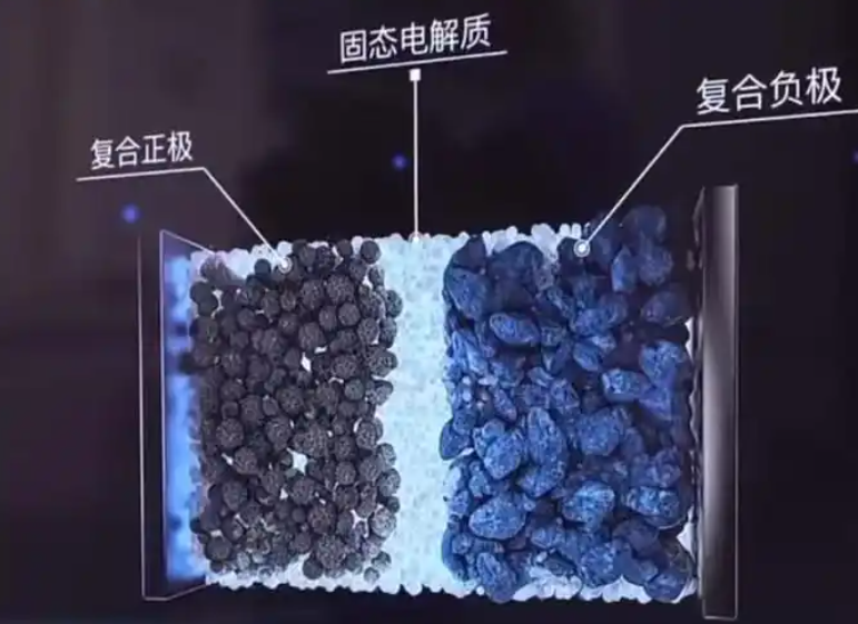
Based on the spatial arrangement of the components, I classify composite solid electrolytes into two main types: filler-type and layered structures. Filler-type composites involve mixing or dispersing one phase within another, creating a random or semi-ordered network. Layered structures consist of distinct stacked layers, each with a specific function. I also include core-shell structures as a specialized variant. In the following sections, I discuss each in detail, drawing on my synthesis of the literature and my own insights.
Polymer/Inorganic Composite Solid Electrolytes
My exploration begins with polymer/inorganic composites, which combine the flexibility of polymers with the high ionic conductivity and mechanical strength of inorganic fillers. These materials are particularly promising for solid state battery applications because they can be processed into thin films and can accommodate electrode volume changes. The synergy arises from complementary properties: oxides provide mechanical reinforcement and a wide electrochemical window, while polymers ensure good interfacial contact and flexibility. I have found that the choice of filler dimension is a critical design parameter, as it dictates the connectivity of ion transport pathways.
Filler-Type Structures
In filler-type polymer/inorganic composites, inorganic particles are dispersed within a polymer matrix. The geometry of the filler—ranging from zero-dimensional (0D) nanoparticles to three-dimensional (3D) networks—critically influences ion transport. I have summarized the dimensional effects in Table 2.
| Filler Dimension | Typical Examples | Key Mechanism | Typical Ionic Conductivity (S/cm) | Advantages | Challenges |
|---|---|---|---|---|---|
| 0D nanoparticles | SiO2, LLZTO, Al2O3 | Suppress polymer crystallization; Lewis acid-base interactions | 10-4 to 10-5 | Simple synthesis, high surface area | Agglomeration, limited long-range pathways |
| 1D nanowires | LLTO nanowires, LLZO nanowires | Long-range continuous ion transport; reduce crystallinity | 10-4 to 10-3 | High aspect ratio, bridge gaps | Complex synthesis, alignment control |
| 2D nanosheets | Garnet nanosheets, graphene oxide | Large interfacial area; layered ion pathways | 10-4 to 10-3 | Enhance mechanical strength, continuous paths | Restacking, dispersion difficulty |
| 3D networks | LLZO networks, bacterial cellulose templates | Self-supporting framework; 3D interconnected ion transport | 10-4 to 10-3 | No agglomeration, high mechanical integrity | Fabrication complexity, template removal |
0D nanoparticles are the most widely studied. They act by physically hindering polymer chain crystallization, thereby increasing the amorphous fraction and improving segmental mobility. For example, incorporating SiO2 nanoparticles into a PEO matrix can reduce crystallinity through strong Lewis acid-base interactions and weak hydrogen bonding, leading to ionic conductivities on the order of 10-4 S/cm and an electrochemical window of 4.8 V vs. Li/Li+. When LLZTO nanoparticles (40 nm) are dispersed in PEO, the room-temperature conductivity reaches 2.1×10⁻⁴ S/cm, nearly two orders of magnitude higher than with micron-sized fillers. The smaller size shortens the lithium-ion diffusion path and increases the interfacial area. Surface modification with silane coupling agents further improves compatibility, yielding conductivities of 2.31×10⁻⁴ S/cm at 30 °C. I attribute this enhancement to the formation of a continuous interphase that facilitates lithium-ion hopping.
1D nanowires offer a more effective strategy for creating long-range ion transport pathways. The high aspect ratio allows them to bridge across the polymer matrix, forming continuous networks. In one comparison, LLTO nanowires (140 nm) at 15 wt% in a PAN/LiClO4 composite increased the ionic conductivity from 2.1×10⁻⁷ S/cm (with nanoparticles) to 2.4×10⁻⁴ S/cm. Solid-state NMR studies have revealed that lithium ions preferentially migrate along the LLZO-modified PAN regions rather than through the bulk polymer, confirming that the nanowires provide surface pathways. This finding has important implications for designing solid state battery electrolytes with percolating ceramic networks.
2D nanosheets, such as garnet nanosheets or graphene oxide, feature ultrathin structures (thickness < 5 nm) and extremely high specific surface areas. When 15 wt% of garnet nanosheets are dispersed in PEO-LiClO4, the room-temperature conductivity reaches 3.6×10⁻⁴ S/cm, three orders of magnitude higher than the pure polymer. The layered stacking of nanosheets provides continuous lithium-ion channels and also enhances mechanical strength through internal interconnection. I have observed that the aspect ratio of nanosheets is a key factor in determining the percolation threshold.
3D network fillers represent the most advanced design. Here, a self-supporting ceramic framework is infiltrated with a polymer electrolyte. This architecture simultaneously optimizes ion transport and mechanical properties. For instance, a 3D LLZO network templated by bacterial cellulose, when infiltrated with PEO and LiTFSI, achieves an ionic conductivity of 1.12×10⁻⁴ S/cm and effectively suppresses lithium dendrites. Another approach uses a sintered LLZO skeleton with in-situ polymerized ETPTA, yielding a room-temperature conductivity of 1.19×10⁻³ S/cm and stable cycling for over 1000 h at 0.3 mA/cm2 in a symmetric cell. The interconnected ceramic network provides a mechanically robust scaffold that can withstand the rigors of repeated cycling.
Layered Structures
Layered polymer/inorganic composites use functional partitioning to address interfacial issues. Instead of random mixing, distinct layers are stacked to optimize different requirements. Sandwich structures, for example, place a rigid inorganic layer between two flexible polymer layers. This design improves interfacial contact, blocks dendrites, and widens the electrochemical window. In one study, a PEO/LATP/PEO sandwich reduced interfacial resistance from 60000 Ω to 270 Ω and increased ionic conductivity to 4×10⁻⁵ S/cm at room temperature. The outer PEO layers ensure good contact with electrodes, while the LATP layer provides high conductivity and mechanical support. I have calculated that the interfacial resistance follows:
$$R_{int} = \frac{\rho_{int}}{A}$$
where \(\rho_{int}\) is the specific interfacial resistivity. The dramatic reduction observed in sandwich structures underscores the importance of intimate contact.
Asymmetric layered electrolytes take this further by using different materials on the anode and cathode sides. An ultra-thin asymmetric solid electrolyte (< 36 μm) with a dense LLZO ceramic layer (5.7 μm) on the anode side and a flexible PEGMEA polymer layer (5.4 μm) on the cathode side has been demonstrated. The rigid layer suppresses dendrites, while the flexible layer ensures ion transport. This design enabled a lithium metal battery to cycle for 3200 h at 0.1 mA/cm2, with a LiFePO4 full cell retaining 94.5% capacity after 120 cycles and coulombic efficiency above 99.8%.
Another variation involves coating a PVDF-HFP/LLZTO composite with PEO-LiTFSI on both sides. The optimal ionic conductivity reached 3.3×10⁻⁴ S/cm, compared to 2.9×10⁻⁶ S/cm for the non-layered counterpart. The PEO-LiTFSI layers improved mechanical properties, electrochemical window, and interfacial performance. To address the instability of LAGP against lithium metal, a Janus LAGP was synthesized with a succinonitrile layer on the cathode side and a polymer interlayer on the anode side. This configuration promoted ion transport and suppressed side reactions.
Table 3 summarizes the performance of various layered polymer/inorganic composites I have reviewed.
| Structure | Materials | Ionic Conductivity (S/cm) | Key Performance | Reference (Generic) |
|---|---|---|---|---|
| Sandwich | PEO/LATP/PEO | 4×10⁻⁵ | Interfacial resistance reduced to 270 Ω | Study A |
| Sandwich | PEO-LiTFSI/PVDF-HFP/LLZTO | 3.3×10⁻⁴ | Enhanced mechanical and interfacial properties | Study B |
| Asymmetric | LLZO/PEGMEA | Not specified | 3200 h cycling, 94.5% capacity retention | Study C |
| Double layer | PVDF/LATP/LiTFSI + PVDF/h-BN/LiTFSI | Not specified | >85% capacity after 250 cycles | Study D |
| Janus | LAGP/SN/polymer | Not specified | Improved interface and dendrite suppression | Study E |
Ion Conduction Mechanisms in Polymer/Inorganic Composites
From my analysis, the enhanced ionic conductivity in polymer/inorganic composites arises from several synergistic mechanisms. The percolation effect becomes dominant when the filler content reaches a threshold, typically between 10 wt% and 30 wt%. However, excessive filler leads to agglomeration, which disrupts stress distribution and degrades performance. The percolation behavior can be modeled as:
$$\sigma = \sigma_0 (f – f_c)^t$$
where \(f_c\) is the critical volume fraction. Interface interactions, such as Lewis acid-base interactions between surface groups on the inorganic filler and the polymer or lithium salt, promote salt dissociation and reduce crystallinity. The entropy effect also plays a role: the composite system exhibits increased disorder, lowering the crystallinity and expanding the amorphous regions, which provide more sites for lithium-ion migration and reduce the activation energy. The overall ion transport is a combination of these effects, and I believe that advanced characterization techniques, such as in-situ electrochemical atomic force microscopy and solid-state NMR, will be essential to further unravel these mechanisms.
I have also considered the role of interfacial polarization. When a composite is subjected to an electric field, charges accumulate at the polymer-filler interface, creating a space charge layer. This can either enhance or impede ion transport depending on the sign of the charge. The space charge potential can be approximated by:
$$\Delta \phi = \frac{\sigma_{free} \lambda_D}{\varepsilon \varepsilon_0}$$
where \(\lambda_D\) is the Debye length and \(\sigma_{free}\) is the free charge density. Understanding these interfacial phenomena is crucial for optimizing composite solid electrolytes for the solid state battery.
Inorganic/Inorganic Composite Solid Electrolytes
I now turn to inorganic/inorganic composites, which combine different inorganic electrolytes to overcome individual limitations. By mixing sulfides, oxides, and halides, one can achieve synergistic improvements in ionic conductivity, mechanical strength, and electrochemical stability. These composites are particularly attractive for solid state battery applications where high modulus and wide voltage windows are required. My analysis shows that the interface between different inorganic phases can be engineered to create fast ion transport pathways.
Filler-Type Inorganic/Inorganic Composites
Filler-type inorganic/inorganic composites involve dispersing one inorganic electrolyte within another. This approach can create continuous ion transport channels and enhance mechanical stability. Table 4 lists several representative systems and their performance.
| Base Electrolyte | Filler | Mass Ratio | Composite Method | Ionic Conductivity (S/cm) | Reference |
|---|---|---|---|---|---|
| LLZO | LATP | 50:50 | Ball milling | 1.3×10⁻⁶ | Study F |
| LLZO | LPS | 40:60 | Mixing | 5.36×10⁻⁴ | Study G |
| LZNO | LPS | 90:10 | Ball milling | 2.44×10⁻⁴ | Study H |
| LLZO | Li6PS5Cl | 40:60 | Ball milling | 1.27×10⁻³ | Study I |
| LLZTO | Li6PS5Cl | 5:95 | Ball milling | 5.4×10⁻⁴ | Study J |
| TaLZ | Li6PS5Cl | 20:80 | Ball milling | 4.42×10⁻⁴ | Study K |
| LATP | LPS | 20:80 | Grinding + ball milling | 3.35×10⁻³ | Study L |
| LPS | LLZO | 70:30 | Ball milling | 1.7×10⁻⁴ | Study M |
| LATP | Li3InCl6 | 80:20 | Grinding | 1.4×10⁻⁴ | Study N |
Same-type composites, such as LATP and LLZO, can be co-sintered to reduce sintering temperature and improve density. By adjusting the sintering temperature from 1300 °C to 800 °C, a relative density of 88.4% and an ionic conductivity of 1.3×10⁻⁶ S/cm were achieved. Different-type composites often show more dramatic improvements. For example, mechanically mixing Li3PS4 (LPS) with LLZO creates a “hard oxide-soft sulfide” system. The LPS forms a flexible coating around LLZO particles (about 50 nm thick), filling the gaps and boosting the ionic conductivity to 5.6×10⁻⁴ S/cm. Optimizing the ratio of LLZO to Li6PS5Cl to 4:6 yields a three-dimensional interpenetrating network with an ionic conductivity of 1.27×10⁻³ S/cm, four orders of magnitude higher than pure LLZO. Adding 5 wt% LLZTO to Li6PS5Cl increases the conductivity to 5.4×10⁻⁴ S/cm and enables stable cycling for 100 h at 0.103 mA/cm2 with an interfacial resistance below 50 Ω.
Non-ionic fillers, such as Al2O3 or SiO2, can also enhance conductivity through space charge effects, but excessive amounts cause blocking effects. Cold sintering has been used to create LATP/Li3InCl6 composites, where the plastic deformation of the halide bridges oxide grain boundaries, achieving 1.4×10⁻⁴ S/cm and stable cycling for over 1600 h. I find that the cold sintering approach is particularly promising for scaling up because it avoids high-temperature degradation.
Layered Inorganic/Inorganic Composites
Layered inorganic/inorganic composites stack different electrolyte materials to optimize interfacial compatibility. For instance, a Li3PS4/LGPS bilayer heterostructure improves the interface with the anode and reduces grain boundary resistance. Inserting a Li6PS5Cl buffer layer between lithium metal and Li3InCl6 suppresses reduction decomposition, enabling symmetric cells to cycle for over 1000 cycles with low overpotential. A sulfide-halide heterostructure with Li3InCl6 on the cathode side and Li6PS5Cl on the anode side achieved 3000 cycles with 80% capacity retention and >80% capacity at 5 C. However, interfacial reactions can still occur. In Li3YCl6/Li6PS5Cl interfaces, side products form during cycling, increasing impedance. Thermodynamic screening and atomic layer deposition of buffer layers are promising solutions. I have summarized these findings in Table 5.
| Anode-Side Material | Cathode-Side Material | Interlayer | Key Performance | Reference |
|---|---|---|---|---|
| Li3PS4 | LGPS | None | Improved anode interface, reduced grain boundary resistance | Study O |
| Li6PS5Cl | Li3InCl6 | Li6PS5Cl | >1000 cycles, low overpotential | Study P |
| Li6PS5Cl | Li3InCl6 | None | 3000 cycles, 80% retention, >80% at 5C | Study Q |
| Li3YCl6 | Li6PS5Cl | None | Side products form, impedance increases | Study R |
Core-Shell Structures
Core-shell structures represent a specialized composite design where a core material is coated with a shell of another electrolyte. This approach can suppress side reactions and improve stability. For example, coating LLZO on sulfide particles with a shell thickness of 2–500 nm inhibits reactions with lithium metal and improves air stability. Coating a halide shell on sulfide particles increased the ionic conductivity to 5.8×10⁻³ S/cm and enabled symmetric cells to cycle for 1600 h at room temperature. Table 6 summarizes core-shell designs.
| Core Material | Shell Material | Shell Thickness | Ionic Conductivity (S/cm) | Key Benefit |
|---|---|---|---|---|
| Sulfide | LLZO | 2–500 nm | Not specified | Suppress side reactions, air stability |
| Sulfide | Halide | Not specified | 5.8×10⁻³ | High conductivity, long cycling |
Ion Conduction Mechanisms in Inorganic/Inorganic Composites
In inorganic/inorganic composites, ion transport is enhanced by several mechanisms. Interfacial pathways form at phase boundaries, where disordered structures lower the diffusion energy barrier. The space charge layer model explains the redistribution of ions at interfaces, leading to enhanced conductivity. The percolation of a high-conductivity phase through a matrix creates continuous pathways. The Nernst-Einstein relation connects conductivity to diffusivity:
$$\sigma = \frac{n e^2 D}{k_B T}$$
where \(n\) is the carrier concentration, \(e\) is the elementary charge, and \(D\) is the diffusion coefficient. Nanostructuring increases interfacial area, and in composites of high-conductivity sulfides with high-strength oxides, the oxide suppresses side reactions while the sulfide fills gaps and forms conductive paths. Space charge layers can drive lithium-ion enrichment at interfaces. I believe that combining multiple characterization techniques and multiscale simulations will be key to optimizing these composites.
I have also examined the role of grain boundaries in inorganic composites. The grain boundary resistance can be modeled as:
$$R_{gb} = \frac{\rho_{gb} \delta}{A d}$$
where \(\rho_{gb}\) is the grain boundary resistivity, \(\delta\) is the grain boundary thickness, and \(d\) is the grain size. Reducing grain size increases the number of grain boundaries, which can either enhance or impede conductivity depending on the grain boundary chemistry. In sulfide-oxide composites, the soft sulfide phase can wet the oxide grain boundaries, reducing the resistance.
Interfacial Engineering and Electrode Compatibility
The performance of a solid state battery depends critically on the interfaces between the composite electrolyte and the electrodes. I have analyzed how different composite structures can be matched with specific electrode materials. Filler-type composites, with their uniform mixing, are well-suited for high-nickel cathodes (NCM811, NCA) and lithium metal anodes. The continuous inorganic network provides high ionic conductivity, while the polymer phase accommodates volume changes. Layered composites, with their functional partitioning, are better for high-voltage cathodes (LiCoO2, lithium-rich manganese-based) and silicon-carbon anodes. The cathode-side layer reduces interfacial resistance, while the anode-side layer optimizes lithium deposition. Table 7 summarizes these matches.
| Composite Structure | Recommended Cathode | Recommended Anode | Key Advantage |
|---|---|---|---|
| Filler-type | High-nickel NCM, NCA | Lithium metal | Continuous ion network, volume accommodation |
| Layered | High-voltage LiCoO2, Li-rich | Silicon-carbon | Functional partitioning, interface optimization |
| Core-shell | Various | Lithium metal | Suppressed side reactions, stability |
Interfacial engineering strategies include buffer layers, surface coatings, and gradient designs. For instance, a LiF-modified LLZT surface improves moisture stability and reduces interfacial resistance to 345 Ω/cm2. A crosslinked PEO-LiTFSI buffer layer ensures uniform lithium deposition. In my view, the development of low-impedance, stable interfaces is as important as bulk conductivity for the success of the solid state battery. The interfacial resistance can be related to the exchange current density by the Butler-Volmer equation:
$$i = i_0 \left[ \exp\left(\frac{\alpha_a n F \eta}{RT}\right) – \exp\left(-\frac{\alpha_c n F \eta}{RT}\right) \right]$$
where \(i_0\) is the exchange current density, \(\eta\) is the overpotential, and \(\alpha\) are transfer coefficients. Minimizing interfacial resistance requires maximizing \(i_0\), which can be achieved by increasing the contact area and improving the chemical compatibility.
Advanced Characterization Techniques
To fully understand the behavior of composite solid electrolytes, I rely on a suite of advanced characterization techniques. These methods provide insights into structure, composition, and ion dynamics at multiple scales. Table 8 lists the key techniques and their applications.
| Technique | Information Obtained | Application in Composite Studies |
|---|---|---|
| SEM-EDS | Morphology, elemental distribution | Assess filler dispersion and uniformity |
| Solid-state NMR | Local structure, ion dynamics | Identify ion transport pathways and sites |
| In-situ EC-AFM | Real-time interfacial evolution | Observe dendrite growth and interface reactions |
| XPS | Surface chemistry, oxidation states | Detect side products and interfacial reactions |
| Neutron diffraction | Bulk crystal structure, light atom positions | Locate lithium ions and study phase transitions |
| Impedance spectroscopy | Conductivity, interfacial resistance | Deconvolute bulk, grain boundary, and interfacial contributions |
I have found that combining these techniques is essential. For example, impedance spectroscopy can identify the overall resistance, but to understand the origin, one needs structural and chemical analysis. In-situ techniques are particularly powerful for studying the dynamic evolution of interfaces during cycling, which is critical for the long-term stability of the solid state battery.
Computational and Theoretical Approaches
Computational methods complement experimental efforts by providing atomic-level insights and predicting new materials. I use density functional theory (DFT) to calculate defect formation energies, migration barriers, and interface stability. Molecular dynamics (MD) simulations reveal ion transport mechanisms and polymer dynamics. Machine learning accelerates the screening of composite compositions. Table 9 summarizes these approaches.
| Method | Scale | Key Outputs | Applications |
|---|---|---|---|
| DFT | Atomic | Formation energies, migration barriers, band gaps | Predict interface stability and ion transport |
| MD | Nanoscale | Diffusion coefficients, radial distribution functions | Study percolation and polymer dynamics |
| Kinetic Monte Carlo | Mesoscale | Ion conductivity, percolation thresholds | Model composite microstructure |
| Machine learning | Multi-scale | Property predictions, composition optimization | Accelerate discovery of new composites |
For instance, DFT calculations can determine the energy barrier for lithium-ion migration across an interface between two electrolytes. If the barrier is too high, the interface will impede transport. MD simulations can model the percolation network in a filler-type composite and predict the percolation threshold. I believe that integrating computational and experimental approaches will significantly shorten the development cycle for solid state battery electrolytes.
Performance Summary and Comparison
To provide a holistic view, I have compiled Table 10, which compares the three main composite structures—filler-type, layered, and core-shell—in terms of advantages, disadvantages, and typical electrochemical performance.
| Structure | Advantages | Disadvantages | Typical Ionic Conductivity (S/cm) | Typical Cycling Performance |
|---|---|---|---|---|
| Filler-type | Simple processing, low cost, high surface area | Filler agglomeration, interfacial incompatibility | >10-4 | Moderate, limited by agglomeration |
| Layered | Dendrite suppression, high interfacial stability | Complex processing, thermal expansion mismatch, thick | >10-4 to 10-3 | >1000 cycles, high voltage tolerance |
| Core-shell | Reduced side reactions, high interfacial compatibility | Complex synthesis, shell thickness control | Up to 5.8×10⁻³ | Long cycle life, stable interfaces |
From this comparison, I conclude that filler-type composites are easiest to fabricate but suffer from agglomeration and limited long-range order. Layered composites offer superior interfacial control but face manufacturing challenges. Core-shell structures provide the best interfacial stability but require precise synthesis. The choice depends on the target application and the required balance of properties. For high-energy-density solid state battery cells, layered structures with thin ceramic separators and flexible polymer coatings appear most promising, provided that the interfacial resistance can be minimized.
Challenges and Future Directions
Despite the progress, several challenges remain before composite solid electrolytes can be commercialized in solid state battery systems. I identify three core contradictions: (1) the trade-off between ultrathin thickness and mechanical integrity; (2) the compatibility of wide temperature operation with high ionic conductivity; and (3) the balance between dynamic interfacial contact resistance and long-term chemical stability. These issues are critical for scaling up. For example, reducing the electrolyte thickness to below 20 μm increases the volumetric energy density but also increases the risk of short circuits due to dendrite penetration. The critical current density for dendrite formation can be estimated by:
$$J_{crit} = \frac{2 \sigma_{el} E_{shear}}{\pi \gamma}$$
where \(\sigma_{el}\) is the electrolyte conductivity, \(E_{shear}\) is the shear modulus, and \(\gamma\) is the surface tension. This equation highlights the importance of high mechanical strength in suppressing dendrites.
To address these challenges, I propose a multi-scale synergistic design approach. First, material innovation: develop new composites with high ionic conductivity, self-healing ability, and wide electrochemical windows. Second, interface engineering: use machine learning to guide interface modification and simulation, constructing low-resistance, stable heterointerfaces. Third, process innovation: develop low-temperature sintering and low-temperature spinning techniques for batch production of ultrathin, dense electrolytes. I also emphasize the need for advanced characterization, such as in-situ techniques and multiscale modeling, to understand ion transport and interfacial evolution.
In terms of future research, I see several promising directions. The use of 3D printing to create structured electrolytes could enable precise control over architecture. The integration of halide electrolytes with sulfides may yield high-voltage stability and high conductivity. The development of flexible composite electrolytes for wearable devices is another avenue. For the solid state battery to reach its full potential, the electrolyte must be optimized not in isolation but as part of the whole cell, considering electrode compatibility, stack pressure, and thermal management.
Furthermore, I believe that computational methods will play an increasingly important role. Density functional theory can predict interface stability and ion migration barriers. Molecular dynamics simulations can reveal percolation pathways and polymer chain dynamics. Machine learning can accelerate the discovery of new composite formulations. By combining theory and experiment, we can shorten the development cycle. I am particularly excited about the possibility of high-throughput screening of composite compositions using machine learning models trained on experimental data.
Another key challenge is the scalability of manufacturing. Most composite solid electrolytes are currently produced at the laboratory scale. To transition to industrial production, we need cost-effective and reproducible processes. Roll-to-roll manufacturing, slot-die coating, and cold sintering are promising techniques. However, each has its own challenges: roll-to-roll requires flexible substrates and careful control of drying, slot-die coating needs stable slurries, and cold sintering requires high pressure. I think that a combination of these methods will be necessary to produce large-area, thin, and dense composite electrolytes.
Conclusion
In this article, I have presented a comprehensive analysis of composite solid electrolytes for all-solid-state batteries. I classified them into filler-type, layered, and core-shell structures, and discussed their material design, interfacial engineering, and ion transport mechanisms. I provided tables summarizing the performance of various systems and equations describing the underlying physics. My key conclusion is that no single material can meet all requirements; composite design is essential. Among the strategies, layered structures offer the best interfacial control, filler-type structures are simplest to process, and core-shell designs provide superior stability. The future of the solid state battery depends on our ability to engineer these composites at multiple scales, from atomic interfaces to macroscopic architectures. I am optimistic that with continued research, composite solid electrolytes will enable safe, high-energy-density solid state battery systems for a sustainable future.
To close, I want to reiterate the importance of the solid state battery in the energy transition. The solid state battery is not just an incremental improvement; it is a paradigm shift. By replacing flammable liquid electrolytes with solid composites, we can achieve unprecedented safety and energy density. I hope my synthesis here will inspire further work in this exciting field. The journey from laboratory discovery to commercial product is long, but the potential rewards are enormous. I am confident that the solid state battery will play a central role in the future of energy storage.