
In my study of electric vehicle propulsion, I treat the permanent magnet synchronous motor as a central energy conversion device. My aim is to explain how high-efficiency control can stabilize torque, speed, and efficiency under real driving conditions. I examine the permanent magnet synchronous motor from its electromagnetic model to advanced digital control laws, and I compare four families of methods: vector control, direct torque control, model predictive control, and intelligent control. Throughout my analysis, I keep returning to the permanent magnet synchronous motor because its high power density, high torque density, and wide speed range make it especially suitable for electric vehicles.
I begin with the principle that the permanent magnet synchronous motor converts electrical energy into mechanical energy through the interaction of a permanent magnet rotor field and a stator winding current field. When three-phase alternating current enters the stator windings, a rotating magnetic field is produced. This rotating field cuts the permanent magnets on the rotor, and the resulting force drives the rotor. In my view, the combination of this machine with new energy vehicles produces a strong synergistic effect, because the permanent magnet synchronous motor can deliver high efficiency without an additional excitation current.
1. Fundamental Model of the Permanent Magnet Synchronous Motor
To control the permanent magnet synchronous motor precisely, I first establish its dynamic model in the rotor reference frame. The d-axis is aligned with the rotor permanent magnet flux, and the q-axis is 90 electrical degrees ahead. In this frame, the voltage equations of the permanent magnet synchronous motor are:
$$v_d = R_s i_d + L_d \frac{di_d}{dt} – \omega_e L_q i_q$$
$$v_q = R_s i_q + L_q \frac{di_q}{dt} + \omega_e (L_d i_d + \psi_f)$$
Here, \(v_d\) and \(v_q\) are the d-axis and q-axis stator voltages, \(i_d\) and \(i_q\) are the corresponding currents, \(R_s\) is the stator resistance, \(L_d\) and \(L_q\) are the d-axis and q-axis inductances, \(\omega_e\) is the electrical angular speed, and \(\psi_f\) is the permanent magnet flux linkage. The flux linkages of the permanent magnet synchronous motor are:
$$\psi_d = L_d i_d + \psi_f$$
$$\psi_q = L_q i_q$$
The electromagnetic torque of the permanent magnet synchronous motor is obtained from the cross product of flux and current:
$$T_e = \frac{3}{2} p (\psi_d i_q – \psi_q i_d)$$
$$T_e = \frac{3}{2} p [\psi_f i_q + (L_d – L_q) i_d i_q]$$
In these expressions, \(p\) is the number of pole pairs. The mechanical dynamics of the permanent magnet synchronous motor are governed by:
$$J \frac{d\omega_m}{dt} = T_e – T_L – B \omega_m$$
$$\omega_e = p \omega_m$$
where \(J\) is the rotor inertia, \(\omega_m\) is the mechanical angular speed, \(T_L\) is the load torque, and \(B\) is the viscous friction coefficient. I summarize the main symbols of the permanent magnet synchronous motor model in the following table.
| Symbol | Meaning | Typical Unit |
|---|---|---|
| \(v_d, v_q\) | Stator voltage components in the dq frame | V |
| \(i_d, i_q\) | Stator current components in the dq frame | A |
| \(R_s\) | Stator resistance | \(\Omega\) |
| \(L_d, L_q\) | d-axis and q-axis inductances | H |
| \(\psi_f\) | Permanent magnet flux linkage | Wb |
| \(\omega_e, \omega_m\) | Electrical and mechanical angular speed | rad/s |
| \(T_e, T_L\) | Electromagnetic torque and load torque | N·m |
| \(J, B\) | Inertia and viscous friction | kg·m², N·m·s/rad |
The coordinate transformations are also essential for controlling the permanent magnet synchronous motor. The Clarke transformation maps three-phase quantities to the stationary \(\alpha\beta\) frame:
$$ \begin{bmatrix} i_\alpha \\ i_\beta \end{bmatrix} = \frac{2}{3} \begin{bmatrix} 1 & -\frac{1}{2} & -\frac{1}{2} \\ 0 & \frac{\sqrt{3}}{2} & -\frac{\sqrt{3}}{2} \end{bmatrix} \begin{bmatrix} i_a \\ i_b \\ i_c \end{bmatrix} $$
The Park transformation then maps the stationary frame to the rotating dq frame:
$$ \begin{bmatrix} i_d \\ i_q \end{bmatrix} = \begin{bmatrix} \cos\theta_e & \sin\theta_e \\ -\sin\theta_e & \cos\theta_e \end{bmatrix} \begin{bmatrix} i_\alpha \\ i_\beta \end{bmatrix} $$
For the permanent magnet synchronous motor, these transformations allow me to separate the stator current into a flux-producing component and a torque-producing component. This separation is the foundation of high-performance control.
2. Advantages of the Permanent Magnet Synchronous Motor in Electric Vehicles
In my assessment, the permanent magnet synchronous motor offers three major advantages in electric vehicles. First, it improves driving range. Because the excitation field is provided by permanent magnets, the permanent magnet synchronous motor does not require an additional excitation current. This reduces losses and raises overall efficiency. During frequent starts, stops, and speed changes, the permanent magnet synchronous motor can still maintain high efficiency, which directly supports longer electric vehicle range.
Second, the permanent magnet synchronous motor improves vehicle dynamic performance. Its compact structure and small volume allow a higher-power machine to be installed in limited space. Its starting torque is large, and its response speed is fast, so it can meet the high-torque demand during launch and acceleration. In my view, this makes the permanent magnet synchronous motor an excellent choice for traction applications.
Third, the permanent magnet synchronous motor enhances reliability and stability. Its structure is relatively simple, which reduces the probability of failure. Permanent magnet materials also maintain good performance under high temperature and high humidity, so the permanent magnet synchronous motor can adapt to complex operating environments.
| Electric Machine Type | Efficiency | Power Density | Torque Density | Control Complexity | Suitability for Electric Vehicles |
|---|---|---|---|---|---|
| Permanent magnet synchronous motor | Very high | Very high | Very high | High | Excellent |
| Induction motor | High | Medium | Medium | Medium | Good |
| Brushless DC motor | High | High | High | Medium | Good |
| Switched reluctance motor | Medium | Medium | Medium | High | Moderate |
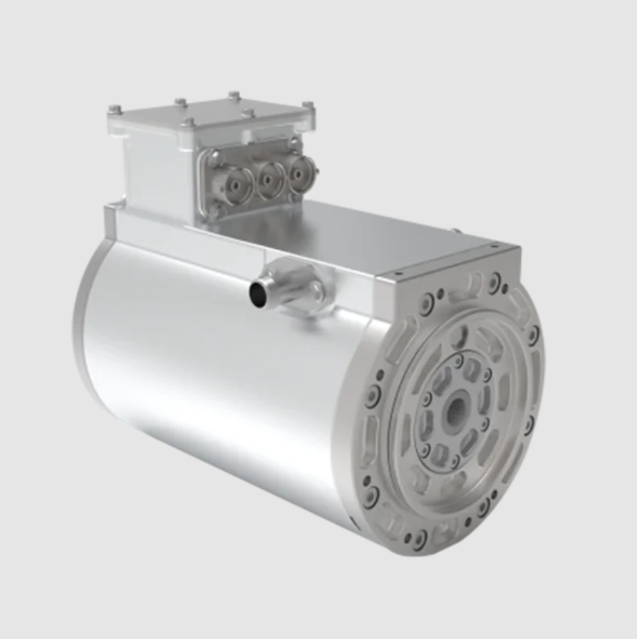
I therefore conclude that the permanent magnet synchronous motor is not only a component but also a strategic enabler for efficient electric mobility. The control method determines whether these advantages are fully realized.
3. Vector Control for the Permanent Magnet Synchronous Motor
Vector control, also called field-oriented control, is the most widely used method for the permanent magnet synchronous motor. In my analysis, its core idea is to transform the three-phase stationary model into a two-phase rotating coordinate system. This allows the stator current to be decomposed into an excitation current component that produces flux and a torque current component that produces torque. The two components can then be controlled independently.
For precise current control, I use proportional-integral regulators. The d-axis and q-axis voltage commands can be written as:
$$v_d^* = K_{pd} e_d + K_{id} \int e_d dt$$
$$v_q^* = K_{pq} e_q + K_{iq} \int e_q dt$$
where the current errors are:
$$e_d = i_d^* – i_d$$
$$e_q = i_q^* – i_q$$
In electric vehicle applications, vector control allows the permanent magnet synchronous motor to maintain high efficiency and good dynamic performance under different operating conditions. For example, during vehicle launch, the controller can rapidly produce a large starting torque. During high-speed cruising, the control logic can reduce iron loss and copper loss to extend range. However, I also observe limitations. Vector control depends on an accurate mathematical model of the permanent magnet synchronous motor. Actual parameters change with temperature and operating time, which can degrade performance. The coordinate transformations and complex algorithms also require high computational capability, increasing hardware cost.
| Aspect | Vector Control for Permanent Magnet Synchronous Motor |
|---|---|
| Main principle | Field orientation and dq-axis current decoupling |
| Current control | PI regulators in the dq frame |
| Dynamic response | Good |
| Steady-state accuracy | High |
| Parameter sensitivity | Moderate to high |
| Computational burden | Medium to high |
| Typical use | Wide-speed electric vehicle traction |
I also consider maximum torque per ampere operation for the permanent magnet synchronous motor. For an interior permanent magnet synchronous motor, the optimal d-axis current is often expressed as:
$$i_d^* = \frac{\psi_f}{2(L_q – L_d)} – \sqrt{\frac{\psi_f^2}{4(L_q – L_d)^2} + i_q^{*2}}$$
This relation helps me achieve high torque with minimum copper loss, which is important for the permanent magnet synchronous motor in frequent start-stop driving.
4. Direct Torque Control for the Permanent Magnet Synchronous Motor
Direct torque control is a high-performance strategy that differs from vector control. In my study, I find that direct torque control acts directly on stator flux and electromagnetic torque in the stator coordinate system. It does not require complex coordinate transformation or current decoupling. The stator flux linkage of the permanent magnet synchronous motor can be estimated from:
$$\psi_s = \int (v_s – R_s i_s) dt$$
The electromagnetic torque can be expressed using the stator flux amplitude, the permanent magnet flux, and the torque angle:
$$T_e = \frac{3}{2} p \frac{|\psi_s|}{L_s} |\psi_f| \sin \delta$$
where \(\delta\) is the angle between the stator flux and the rotor flux. Direct torque control uses the spatial voltage vector concept. It calculates the flux linkage and torque from measured stator voltage and current, compares them with reference values, and then selects an appropriate voltage vector. The control process can be summarized in the following table.
| Step | Action in Direct Torque Control | Purpose for Permanent Magnet Synchronous Motor |
|---|---|---|
| 1 | Measure stator voltage and current | Obtain real-time states |
| 2 | Estimate stator flux and torque | Build feedback variables |
| 3 | Compare with references | Determine flux and torque errors |
| 4 | Identify flux and torque sectors | Locate operating condition |
| 5 | Select optimal voltage vector | Directly regulate flux and torque |
In electric vehicles, direct torque control has a very fast dynamic response. It can adjust torque in a very short time, which satisfies the fast torque response required during hard acceleration and hard deceleration. For example, when the vehicle needs emergency overtaking, direct torque control can quickly increase the torque of the permanent magnet synchronous motor. It also has strong robustness and low dependence on motor parameters. However, because it uses discrete voltage vector selection, torque and flux pulsations can occur. These pulsations affect smoothness and noise performance. To reduce them, I can replace the traditional voltage vector selection with space vector modulation. The reference voltage vector is:
$$v_{ref} = \frac{2}{3}(v_a + a v_b + a^2 v_c), \quad a = e^{j2\pi/3}$$
| Aspect | Direct Torque Control for Permanent Magnet Synchronous Motor |
|---|---|
| Main principle | Direct flux and torque control using voltage vectors |
| Coordinate transformation | Not required |
| Dynamic response | Very fast |
| Parameter sensitivity | Low |
| Torque ripple | Higher than vector control |
| Computational burden | Low to medium |
| Typical improvement | Space vector modulation |
5. Model Predictive Control for the Permanent Magnet Synchronous Motor
Model predictive control is an advanced model-based strategy. In my work, I use it to predict the future output states of the permanent magnet synchronous motor and to solve an optimization problem in each control period. The discrete state-space model of the permanent magnet synchronous motor can be written as:
$$x(k+1) = A x(k) + B u(k) + F d(k)$$
where \(x\) is the state vector, \(u\) is the control input, and \(d\) is the disturbance or load term. A typical state vector for the permanent magnet synchronous motor is:
$$x = \begin{bmatrix} i_d & i_q & \omega_m & \theta_e \end{bmatrix}^T$$
The prediction over a horizon \(N_p\) is:
$$x(k+N_p) = A^{N_p} x(k) + \sum_{j=0}^{N_p-1} A^{N_p-1-j} B u(k+j)$$
I define a cost function that includes torque tracking, flux tracking, current limits, and switching constraints:
$$J = \sum_{i=1}^{N_p} \| y(k+i|k) – y_{ref}(k+i) \|_Q^2 + \sum_{j=0}^{N_c-1} \| \Delta u(k+j|k) \|_R^2$$
The constraints for the permanent magnet synchronous motor can include:
$$|i_d| \le i_{d,max}, \quad |i_q| \le i_{q,max}, \quad |u| \le u_{max}$$
Model predictive control can consider multiple objectives and constraints simultaneously. For the permanent magnet synchronous motor in an electric vehicle, this means I can optimize efficiency, torque response, and current safety at the same time. The main disadvantage is computational burden. Each control period requires a complex optimization solution. I can reduce this burden by using a fast prediction model, a shorter prediction horizon, or an explicit model predictive control law.
| Aspect | Model Predictive Control for Permanent Magnet Synchronous Motor |
|---|---|
| Main principle | Prediction model and online optimization |
| Multi-objective capability | Excellent |
| Constraint handling | Direct and systematic |
| Dynamic response | Fast |
| Computational burden | High |
| Parameter sensitivity | Moderate |
| Typical use | High-performance electric vehicle traction |
In my evaluation, model predictive control is especially attractive for the permanent magnet synchronous motor when the controller has sufficient computing power. It can unify several control goals that are usually handled separately.
6. Intelligent Control for the Permanent Magnet Synchronous Motor
With the rapid development of artificial intelligence, intelligent control has been increasingly applied to the permanent magnet synchronous motor. I focus on fuzzy control, neural network control, and their combination. Fuzzy control does not require an exact mathematical model. It uses fuzzy logic to convert input variables into fuzzy sets, applies fuzzy rules, and then defuzzifies the result. For the permanent magnet synchronous motor, the speed error and speed error rate are common inputs:
$$e = \omega^* – \omega$$
$$\dot{e} = \frac{de}{dt}$$
A fuzzy rule table for the permanent magnet synchronous motor can be organized as follows.
| Speed Error \(e\) | Error Rate \(\dot{e}\) | Control Action |
|---|---|---|
| Negative Large | Negative | Increase voltage command strongly |
| Negative Small | Negative | Increase voltage command slightly |
| Zero | Zero | Hold voltage command |
| Positive Small | Positive | Decrease voltage command slightly |
| Positive Large | Positive | Decrease voltage command strongly |
Neural network control uses the learning and approximation ability of neural networks to model the complex mapping between inputs and outputs of the permanent magnet synchronous motor. A multi-layer perceptron can take given speed, current speed, and current as inputs and output the inverter control signal. The neuron output can be written as:
$$y = f\left(\sum_{i=1}^n w_i x_i + b\right)$$
where \(f\) is the activation function, \(w_i\) are weights, \(x_i\) are inputs, and \(b\) is the bias. A fuzzy neural network combines fuzzy reasoning with neural learning. A common fuzzy neural network representation is:
$$\mu_{ij}(x_i) = \exp\left(-\frac{(x_i – c_{ij})^2}{2\sigma_{ij}^2}\right)$$
$$y_k = \frac{\sum_j \bar{w}_{jk} \prod_i \mu_{ij}(x_i)}{\sum_j \prod_i \mu_{ij}(x_i)}$$
In my view, intelligent control is powerful for the permanent magnet synchronous motor when operating conditions are complex and uncertain. Fuzzy control has strong robustness and adaptability. Neural network control can learn nonlinear behavior. Fuzzy neural control can automatically adjust fuzzy rules and membership functions. However, I also note that fuzzy rule design and neural network training require extensive experience and data, and the design and debugging of intelligent control systems are relatively complex.
| Intelligent Method | Key Strength | Main Limitation | Suitability for Permanent Magnet Synchronous Motor |
|---|---|---|---|
| Fuzzy control | Robustness to parameter variation | Rule design depends on expertise | Good for uncertain loads |
| Neural network control | Nonlinear mapping and learning | Requires large training data | Good for complex nonlinear dynamics |
| Fuzzy neural control | Combines reasoning and learning | Higher design complexity | Excellent for adaptive traction control |
7. Comparative Assessment of Control Methods
To compare the four control families for the permanent magnet synchronous motor, I use several criteria: dynamic response, steady-state accuracy, parameter sensitivity, computational cost, torque ripple, and implementation maturity. The following table summarizes my assessment.
| Criterion | Vector Control | Direct Torque Control | Model Predictive Control | Intelligent Control |
|---|---|---|---|---|
| Dynamic response | Good | Very fast | Fast | Adaptive |
| Steady-state accuracy | High | Medium | High | Medium to high |
| Parameter sensitivity | Moderate to high | Low | Moderate | Low to moderate |
| Computational cost | Medium | Low | High | High |
| Torque ripple | Low | Medium to high | Low | Dependent on tuning |
| Implementation maturity | Very mature | Mature | Emerging | Emerging |
| Best use case | Wide-speed traction | Fast torque transients | Multi-objective optimization | Uncertain and nonlinear conditions |
In my integrated design view, no single method is universally optimal for the permanent magnet synchronous motor. A layered architecture can combine the strengths of each method. For example, I can use vector control as the baseline current regulator, direct torque control during fast transient events, model predictive control for constraint-aware optimization, and intelligent control for parameter adaptation. This layered structure keeps the permanent magnet synchronous motor efficient across the full operating range.
8. Efficiency and Loss Modeling for the Permanent Magnet Synchronous Motor
Because high efficiency is a primary goal, I also model the losses of the permanent magnet synchronous motor. The efficiency is:
$$\eta = \frac{P_{out}}{P_{in}} = \frac{T_e \omega_m}{V_{dc} I_{dc}}$$
The total loss can be divided into copper loss, iron loss, mechanical loss, and stray loss:
$$P_{loss} = P_{cu} + P_{fe} + P_{mech} + P_{stray}$$
For the permanent magnet synchronous motor, copper loss in the dq frame is:
$$P_{cu} = \frac{3}{2} R_s (i_d^2 + i_q^2)$$
Iron loss can be approximated as:
$$P_{fe} = k_h f B_m^2 + k_e f^2 B_m^2 + k_a f^{1.5} B_m^{1.5}$$
where \(k_h\), \(k_e\), and \(k_a\) are hysteresis, eddy current, and anomalous loss coefficients, \(f\) is frequency, and \(B_m\) is flux density amplitude. In my control design, I try to minimize the sum of these losses while satisfying torque and voltage constraints. This is especially important for the permanent magnet synchronous motor because its high efficiency advantage can be lost if the controller drives it into unnecessary loss regions.
| Loss Component | Physical Origin | Control-Related Reduction Method |
|---|---|---|
| Copper loss | Stator winding resistance | Maximum torque per ampere, current shaping |
| Iron loss | Hysteresis and eddy currents | Flux weakening, optimal d-axis current |
| Mechanical loss | Friction and windage | Speed profile optimization |
| Stray loss | Harmonics and leakage | SVM, harmonic suppression |
9. Sensorless and Adaptive Control Considerations
In my study, I also consider sensorless control for the permanent magnet synchronous motor. Eliminating the position sensor reduces cost and improves reliability. A common approach is to estimate the rotor position from the back electromotive force:
$$e_\alpha = v_\alpha – R_s i_\alpha – L_s \frac{di_\alpha}{dt}$$
$$e_\beta = v_\beta – R_s i_\beta – L_s \frac{di_\beta}{dt}$$
$$\theta_e = \tan^{-1}\left(\frac{-e_\alpha}{e_\beta}\right)$$
For the permanent magnet synchronous motor, back electromotive force estimation becomes difficult at low speed. Therefore, I combine high-frequency injection, sliding-mode observers, or model reference adaptive systems. An adaptive PI controller can be written as:
$$K_p(t) = K_{p0} + \Delta K_p(e,t)$$
$$K_i(t) = K_{i0} + \Delta K_i(e,t)$$
where the gains are adjusted online according to speed error and its derivative. This improves robustness of the permanent magnet synchronous motor against temperature, saturation, and load variation.
10. Thermal and Fault-Tolerant Control of the Permanent Magnet Synchronous Motor
Thermal limits are critical for the permanent magnet synchronous motor because permanent magnets can demagnetize at high temperature. I use a thermal model:
$$C_{th} \frac{dT}{dt} = P_{loss} – \frac{T – T_{amb}}{R_{th}}$$
where \(C_{th}\) is thermal capacitance, \(R_{th}\) is thermal resistance, \(T\) is machine temperature, and \(T_{amb}\) is ambient temperature. In my control strategy, I derate the current when temperature approaches a limit:
$$i_{max}(T) = i_{max0} \sqrt{\frac{T_{max} – T}{T_{max} – T_{nom}}}$$
Fault-tolerant control for the permanent magnet synchronous motor includes open-phase fault, short-circuit fault, and inverter switch fault. I can use redundant phases, current reconfiguration, or fault-tolerant inverter topology to maintain operation. A simple fault detection residual is:
$$r = |i_{measured} – i_{estimated}|$$
If \(r\) exceeds a threshold, I reconfigure the control law and reduce torque demand. This maintains safety and reliability of the permanent magnet synchronous motor in electric vehicles.
11. My Integrated Control Framework
Based on my analysis, I propose an integrated control framework for the permanent magnet synchronous motor. The framework has four layers:
| Layer | Function | Main Method |
|---|---|---|
| Reference generation | Speed and torque demand | Driver intent, efficiency map |
| Optimization | Constraint-aware current and voltage selection | Model predictive control |
| Regulation | Fast current and torque tracking | Vector control or direct torque control |
| Adaptation | Parameter and disturbance compensation | Intelligent control, adaptive laws |
In this framework, the permanent magnet synchronous motor is controlled not only for torque but also for efficiency, thermal safety, and fault tolerance. I use a cost function that combines torque error, loss, current limit, voltage limit, and temperature:
$$J = w_1 (T_e^* – T_e)^2 + w_2 P_{loss} + w_3 (i_d^2 + i_q^2) + w_4 (T – T_{max})^2$$
The weights \(w_1\) to \(w_4\) can be tuned for different driving modes. For example, in eco mode, I increase \(w_2\) to prioritize efficiency. In sport mode, I increase \(w_1\) to prioritize torque response. This gives the permanent magnet synchronous motor flexible behavior across diverse electric vehicle missions.
12. Practical Implementation Notes
From my implementation perspective, the following practical points matter for the permanent magnet synchronous motor:
| Implementation Issue | Recommended Action |
|---|---|
| Parameter variation | Online identification of \(R_s\), \(L_d\), \(L_q\), \(\psi_f\) |
| Inverter nonlinearity | Dead-time compensation |
| Current sampling noise | Synchronized sampling and filtering |
| Computational delay | Two-step prediction or delay compensation |
| Torque ripple | SVM, harmonic current injection |
| Thermal stress | Derating and thermal observer |
I also recommend using a digital signal processor or field-programmable gate array for the permanent magnet synchronous motor control. The switching frequency should be selected to balance loss and acoustic noise. For model predictive control, a short prediction horizon often gives sufficient performance with lower computation.
13. Conclusion
In my conclusion, the permanent magnet synchronous motor is a key enabler of efficient electric vehicles. Its high power density, high torque density, and high efficiency are valuable, but these benefits depend on the control method. I have examined vector control, direct torque control, model predictive control, and intelligent control. Each method has strengths and limitations. Vector control offers mature and accurate current regulation. Direct torque control offers very fast torque response and low parameter sensitivity. Model predictive control offers multi-objective optimization and constraint handling. Intelligent control offers adaptation and robustness under uncertainty.
I believe the best direction is an integrated, layered control architecture for the permanent magnet synchronous motor. Such an architecture can combine accurate modeling, fast transient response, online optimization, and intelligent adaptation. It can also include loss minimization, thermal management, sensorless estimation, and fault tolerance. By continuously developing these methods, I expect the permanent magnet synchronous motor to remain a leading solution for electric vehicle traction, and I expect its control systems to become more efficient, more reliable, and more intelligent.
In my final assessment, the permanent magnet synchronous motor should not be treated as a fixed component with a single control law. Instead, it should be treated as a cyber-physical system whose electromagnetic, thermal, and mechanical states are coordinated in real time. This is the perspective I apply when I study high-efficiency control for the permanent magnet synchronous motor in new energy vehicles.