
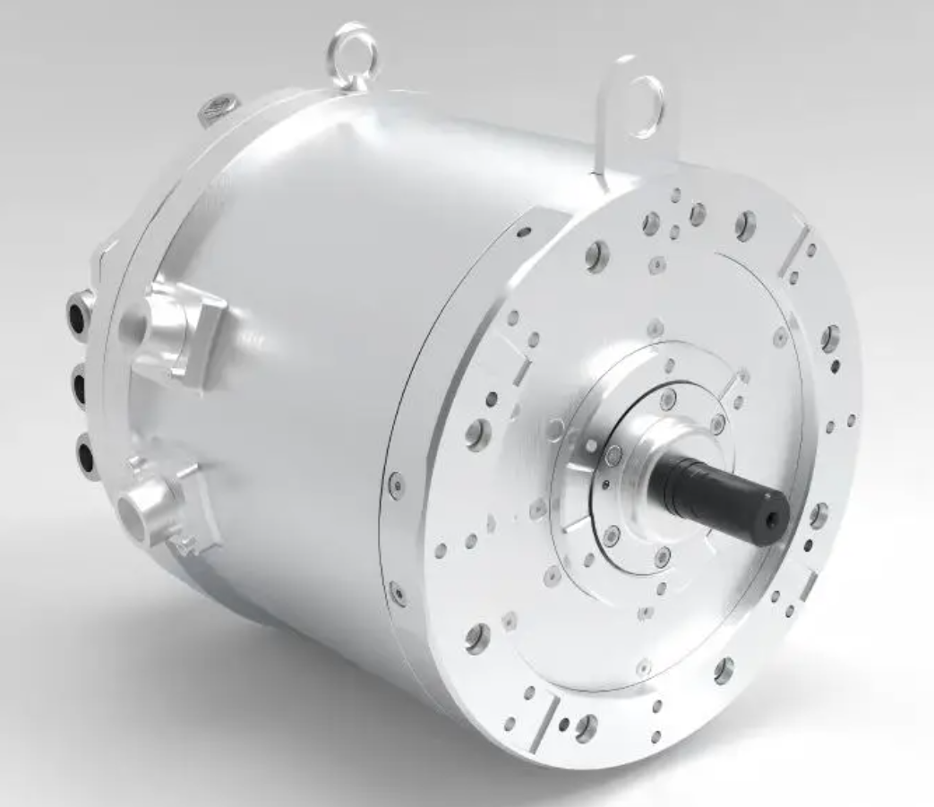
In the development of electric vehicles, the noise–vibration–harshness (NVH) performance of the drive motor has become a decisive factor for passenger comfort. Among various traction motor topologies, the permanent magnet synchronous motor is widely adopted because of its high efficiency and high power density. However, the permanent magnet synchronous motor also introduces electromagnetic vibration and acoustic noise that are strongly related to the interaction between the rotor field and the stator field. In my work, I focus on a fast and agile electromagnetic vibration simulation method that directly targets the resonance risk speed rather than sweeping the entire speed range or relying only on the corner speed of the peak or rated external characteristic.
The method I propose begins with an electromagnetic vibration mechanism analysis to identify the critical time frequencies and spatial distributions of the electromagnetic force waves. Then, I perform a modal simulation of the motor stator structure to find the modal shapes and frequencies that are likely to couple with the electromagnetic force. Based on the time–space analysis of the electromagnetic force and the stator modal analysis, I determine the resonance risk speed. At this speed, I conduct an electromagnetic force simulation and map the force onto the stator teeth for an electromagnetic vibration simulation. Finally, I optimize the stator dimensions according to the vibration simulation results to mitigate the electromagnetic vibration. Throughout this article, the permanent magnet synchronous motor is the central subject, and I use detailed formulas and tables to summarize the key relationships.
1. Introduction
NVH is an important indicator of the ride comfort of new energy vehicles. The drive motor is the main power source and also a major noise source, so its vibration and noise have a significant influence on the overall vehicle NVH. Although the sound pressure level of motor noise is lower than that of a traditional internal combustion engine, the maximum speed of a vehicle drive motor can be several times higher than that of an engine. Therefore, the noise frequency of the drive motor is higher, and users are more likely to perceive it as unpleasant. To evaluate NVH performance in the early design stage, I need to carry out NVH simulation analysis of the electromagnetic and structural design schemes. This means mapping the electromagnetic force onto the stator teeth and then performing electromagnetic vibration and noise radiation simulations. Since motor noise is generated by vibration, I can evaluate only the electromagnetic vibration in the design stage for high efficiency. In addition, in the early design stage, an electromagnetic design scheme often exists before a detailed structural design scheme. Without a structure acting as an acoustic radiation surface, electromagnetic vibration simulation is still feasible for NVH evaluation of the electromagnetic scheme.
The operating speed range of a vehicle drive motor is wide. Many studies select the corner speed of the peak or rated external characteristic curve for electromagnetic vibration simulation. However, analysis of motor bench and vehicle NVH measurement data shows that the corner speed does not necessarily coincide with a stator mode that couples with the electromagnetic force. Therefore, the probability of NVH problems at the peak or rated corner speed is not high. Some studies select the full speed range, but this approach requires many simulation speed points and has the disadvantage of a large computational workload. I avoid full-speed simulation and peak or rated corner speed simulation, and instead I propose a fast and efficient electromagnetic vibration simulation method that directly targets the resonance risk speed. In this article, I present the permanent magnet synchronous motor as the object of study and describe the complete workflow.
2. Electromagnetic Vibration Mechanism Analysis
The permanent magnet synchronous motor is a common drive motor for new energy vehicles because of its high efficiency. When the permanent magnet synchronous motor rotates with current, the air-gap magnetic field between the stator and rotor generates a rotating electromagnetic force wave that acts on the motor stator and excites the corresponding mode and vibration deformation. The rotating electromagnetic force wave has two components: a radial force and a tangential force. The radial force easily couples with the stator mode and causes large radial vibration deformation, so it is the main source of electromagnetic vibration. The tangential force excites tangential vibration as a secondary source. Therefore, I generally take the electromagnetic vibration caused by the radial force as the main object of analysis.
2.1 Radial Electromagnetic Force Wave Analysis
The rotating radial electromagnetic force wave is the main factor producing vibration and noise in the permanent magnet synchronous motor. It has two important characteristics: time distribution and spatial distribution. According to the Maxwell stress tensor method, the instantaneous value of the radial electromagnetic force wave per unit area in the air gap, denoted as \(p_r(t,\theta)\), can be expressed as a function of time \(t\) and spatial angle \(\theta\):
$$ p_r(t,\theta) = \frac{b^2(t,\theta)}{2\mu_0} \tag{1} $$
where \(\mu_0\) is the air permeability, and \(b(t,\theta)\) is the air-gap magnetic flux density, which is also a function of time \(t\) and spatial angle \(\theta\). The air-gap magnetic flux density can be written as the product of the magnetomotive force and the permeance:
$$ b(t,\theta) = f(t,\theta)\,\lambda(t,\theta) \tag{2} $$
where \(f(t,\theta)\) is the magnetomotive force in the air gap, and \(\lambda(t,\theta)\) is the permeance in the air gap. When the permanent magnet synchronous motor is supplied with sinusoidal current and has a pole pair number \(p\), the magnetomotive force can be expressed as the sum of the rotor magnetomotive force and the stator magnetomotive force:
$$ f(t,\theta) = \sum_{\mu} f_{\mu}(t,\theta) + \sum_{v} f_{v}(t,\theta) = \sum_{\mu} F_{\mu} \cos(\mu p \theta – \mu \omega t) + \sum_{v} F_{v} \cos(v p \theta – \omega t – \phi_v) \tag{3} $$
where \(f_{\mu}\) is the \(\mu\)-th harmonic rotor magnetomotive force, \(F_{\mu}\) is the amplitude of the \(\mu\)-th harmonic rotor magnetomotive force, \(f_{v}\) is the \(v\)-th harmonic stator magnetomotive force, \(F_{v}\) is the amplitude of the \(v\)-th harmonic stator magnetomotive force, \(\omega\) is the angular frequency of the fundamental magnetomotive force, and \(\phi_v\) is the phase angle of the \(v\)-th harmonic stator magnetomotive force.
For an integer-slot motor, the stator winding magnetic field harmonic order \(v\) is given by:
$$ v = 6k_1 + 1, \quad k_1 = \pm 1, \pm 2, \pm 3, \ldots \tag{4} $$
where \(k_1\) is an integer representing the stator magnetic field harmonic order. According to this expression, the stator magnetic field harmonic orders \(v\) can take values such as \(1, 7, -5, 13, -11, 19, -17\), and so on. The rotor magnetic field harmonic order \(\mu\) is given by:
$$ \mu = 2k_2 + 1, \quad k_2 = 0, 1, 2, 3, \ldots \tag{5} $$
where \(k_2\) is an integer representing the rotor magnetic field harmonic order. From this expression, the rotor magnetic field harmonic orders \(\mu\) can take values such as \(1, 3, 5, 7, 9, 11, 13, 15, 17, 19\), and so on. For a permanent magnet motor with a uniform air gap and a slotted stator, the permeance function \(\lambda(t,\theta)\) in Eq. (3) can be expressed as:
$$ \lambda(t,\theta) = \lambda_0 + \sum_{k=1,2,3,\ldots}^{\infty} \lambda_k \cos(k z \theta) \tag{6} $$
where \(\lambda_0\) is the constant component of the air-gap permeance, \(\lambda_k\) is the harmonic component, \(z\) is the number of stator slots, and \(k\) is the permeance harmonic order. Substituting Eqs. (2)–(6) into Eq. (1), the radial force wave \(p_r\) generated by the interaction between the stator and rotor magnetic fields is obtained as:
$$ p_r = \frac{1}{2\mu_0} \sum_{\mu} \sum_{v} \sum_{k} B \cos\left[(\mu \pm v) p \theta – (\mu \pm 1) \omega t\right] \tag{7} $$
where \(B\) is the rotor magnetic flux density. The spatial distribution of the radial force wave can be represented by the force wave order \(r\). According to Eq. (7), the radial force wave order \(r\) generated by the interaction between the stator and rotor magnetic fields is:
$$ r = (\mu + v)p \quad \text{or} \quad r = (\mu – v)p \tag{8} $$
The corresponding force wave frequency \(f_r\) is:
$$ f_r = (\mu + 1)f \quad \text{or} \quad f_r = (\mu – 1)f \tag{9} $$
where \(f\) is the electrical frequency. For an 8-pole 48-slot permanent magnet synchronous motor, \(f = 4\). From Eqs. (4), (5), and (8), the electromagnetic radial force wave order of an integer-slot motor is either 0 or an integer multiple of the motor pole number. For the 8-pole 48-slot motor, the radial force waves are of orders 0, 8, and 16. The lower the radial force wave order, the larger the stator deformation and the electromagnetic vibration it generates. Therefore, the 0-order force wave easily produces large electromagnetic vibration. Combining Eq. (9), the frequency components of the 0-order force wave include the 6th harmonic of the electrical frequency (24th order), the 12th harmonic (48th order), and the 24th harmonic (96th order). These originate from the 5th and 7th harmonics, the 11th and 13th harmonics, and the 17th and 19th harmonics of the stator and rotor magnetic fields, respectively.
To summarize the key force wave orders and their sources, I present Table 1. This table lists the spatial order, the corresponding time frequency order, and the magnetic field harmonic sources for the 8-pole 48-slot permanent magnet synchronous motor.
| Radial force wave order \(r\) | Time frequency order (multiple of electrical frequency) | Source magnetic field harmonics | Relative energy level |
|---|---|---|---|
| 0 | 24 | 5th and 7th | Moderate |
| 0 | 48 | 11th and 13th | High |
| 0 | 96 | 17th and 19th | Low |
| 8 | 24, 48, 96 | Various combinations | Lower than order 0 |
| 16 | 24, 48, 96 | Various combinations | Lower than order 0 |
Table 1 clearly shows that the 48th-order time frequency of the 0-order force wave is a major concern because it has relatively high energy and can couple with the 0-order breathing mode of the stator. I will use this information in the subsequent resonance risk speed calculation.
2.2 Modal Analysis of the Stator Structure
Electromagnetic vibration is mainly generated when the electromagnetic radial force excites the stator mode. In modal analysis, the motor structure can be regarded as a vibration system with multiple degrees of freedom. Let the number of degrees of freedom of this vibration system be \(n\). Then its second-order vibration differential equation can be expressed in general matrix form:
$$ M \ddot{X} + C \dot{X} + K X = F(t) \tag{10} $$
where \(M\) is the mass matrix, \(C\) is the damping matrix, \(K\) is the stiffness matrix, \(X\) is the vibration displacement vector, and \(F(t)\) is the excitation force vector. Damping is generally obtained by modal testing and cannot be obtained by simulation. Therefore, I do not consider damping in the simulation modal analysis. In addition, free modal analysis does not consider the influence of boundary conditions and can reflect the general laws of the vibration system. Therefore, for an undamped free vibration system, I obtain:
$$ M \ddot{X} + K X = 0 \tag{11} $$
The particular solution in vector form is \(x(t) = \phi_i e^{j\omega_0 t}\), and the characteristic equation is:
$$ (K – \omega_0^2 M) \phi_i = 0 \tag{12} $$
The necessary and sufficient condition for Eq. (12) to have a non-zero solution is \(|K – \omega_0^2 M| = 0\). Accordingly, I can obtain the eigenvalue \(\omega_i\), which is the \(i\)-th modal frequency, and the eigenvector \(\phi_i\), which is the \(i\)-th modal shape.
Based on the above modal analysis theory, I use structural finite element analysis software to apply silicon steel material properties to the motor stator structure. The density is \(7650\,\text{kg/m}^3\), the Poisson’s ratio is \(0.27\), and the elastic modulus is \(1.65 \times 10^{11}\,\text{Pa}\). The free modal analysis results of the stator are summarized in Table 2. The 2nd-order elliptical mode frequency is \(754.52\,\text{Hz}\), the 4th-order square mode frequency is \(3624.7\,\text{Hz}\), and the 0-order breathing mode frequency is \(6706.8\,\text{Hz}\). Because the low-order modes have the same phase and greater energy, they easily produce larger electromagnetic vibration. Therefore, I need to pay special attention to the 0-order breathing mode.
| Mode order | Mode shape | Frequency (Hz) | Observation |
|---|---|---|---|
| 2 | Elliptical | 754.52 | Low-order deformation |
| 4 | Square | 3624.7 | Higher-order deformation |
| 0 | Breathing | 6706.8 | Critical for 0-order force wave |
Table 2 shows that the 0-order breathing mode is at \(6706.8\,\text{Hz}\). This frequency is much higher than the elliptical and square modes, but it is the most important for the 0-order radial force wave because the spatial distribution matches. When the electromagnetic force wave and the stator mode have the same time frequency and spatial distribution, strong resonance occurs. The 0-order force wave, as a low-order force wave, easily resonates with the 0-order stator mode. The resonance amplitude is much larger than that of a higher-order 8-order force wave meeting an 8-order stator mode.
2.3 Electromagnetic Vibration Analysis
According to the radial force wave sources, the time frequencies corresponding to the spatial 0-order force wave are the 24th, 48th, and 96th orders. Combined with the measured radial vibration color map, I observe that due to the limitation of the maximum motor speed, the 24th-order time frequency cannot reach the 0-order stator mode around \(6706.8\,\text{Hz}\). Therefore, the 24th order cannot produce resonance. Although the 96th order can reach the 0-order mode, the 96th order is a harmonic of the 48th order and originates from the 17th and 19th high-order magnetic field harmonics. Therefore, its energy is small and it cannot excite large resonance. Consequently, the main electromagnetic vibration is generated by the resonance between the 48th-order time frequency and the 0-order stator mode. The resonance frequency band of the 48th order at medium and high speeds is the key region for my analysis.
To quantify the relationship, I express the resonance condition as follows. Let \(f_{\text{mode}}\) be the modal frequency of the stator, and let \(f_{\text{force}}\) be the time frequency of the electromagnetic force wave. Resonance occurs when:
$$ f_{\text{force}} = f_{\text{mode}} \tag{13} $$
For the 0-order breathing mode, \(f_{\text{mode}} = 6706.8\,\text{Hz}\). The 48th-order time frequency is related to the mechanical rotation speed \(n\) (in r/min) and the electrical frequency \(f\) by:
$$ f = \frac{p n}{60} \tag{14} $$
For the 8-pole permanent magnet synchronous motor, \(p = 4\). The 48th-order time frequency is \(48f\). Therefore, the resonance risk speed \(n_{\text{res}}\) is:
$$ n_{\text{res}} = \frac{60 f_{\text{mode}}}{48 p} = \frac{60 \times 6706.8}{48 \times 4} = 8383.5\,\text{r/min} \tag{15} $$
This calculated speed is neither the peak nor the rated corner speed, nor an integer multiple of \(100\,\text{r/min}\), \(200\,\text{r/min}\), or \(500\,\text{r/min}\). This demonstrates the advantage of my method: it directly identifies the resonance risk speed instead of using arbitrary speed points.
3. Electromagnetic Vibration Simulation Analysis
Based on the radial force wave, stator modal, and electromagnetic resonance mechanism analysis, I propose a fast and efficient electromagnetic vibration simulation method that directly targets the resonance risk point. The steps are as follows.
First, through electromagnetic vibration mechanism analysis, I obtain the key time frequency and spatial distribution of the electromagnetic force wave. Second, through the modal simulation analysis of the motor stator structure, I obtain the modal shapes and frequencies that easily couple and resonate with the electromagnetic force. Third, based on the time–space analysis of the electromagnetic force and the stator modal analysis, I calculate the resonance risk speed. Taking the 0-order modal frequency of \(6706.8\,\text{Hz}\) as the benchmark, I calculate the risk speed as \(8383.5\,\text{r/min}\). This speed point is neither the peak nor the rated corner speed, nor an integer multiple of \(100\,\text{r/min}\), \(200\,\text{r/min}\), or \(500\,\text{r/min}\). Fourth, at the resonance risk speed of \(8383.5\,\text{r/min}\) and the corresponding peak external characteristic, I perform an electromagnetic force simulation and map the electromagnetic force onto the stator teeth. The maximum instantaneous electromagnetic force is \(1.63\,\text{N}\). Based on the modal superposition method, I perform an electromagnetic vibration simulation and obtain the electromagnetic vibration displacement. The maximum electromagnetic vibration displacement amplitude is \(0.0349\,\text{mm}\). Because damping is not considered, this vibration value is relatively large, but the vibration amplitude can be used as a reference for scheme comparison.
To make the simulation workflow reproducible, I summarize the input parameters and output results in Table 3. This table includes the key electrical, geometric, and modal parameters used in my simulation.
| Parameter | Symbol | Value | Unit |
|---|---|---|---|
| Pole pair number | \(p\) | 4 | – |
| Stator slots | \(z\) | 48 | – |
| Electrical frequency at resonance | \(f\) | \(6706.8/48 = 139.725\) | Hz |
| Resonance risk speed | \(n_{\text{res}}\) | 8383.5 | r/min |
| Maximum instantaneous electromagnetic force | \(F_{\max}\) | 1.63 | N |
| Maximum vibration displacement before optimization | \(d_{\max,0}\) | 0.0349 | mm |
| 0-order breathing mode frequency before optimization | \(f_{0,0}\) | 6706.8 | Hz |
Table 3 confirms that the resonance risk speed is determined by the modal frequency and the force wave order. The permanent magnet synchronous motor under study has a 0-order breathing mode at \(6706.8\,\text{Hz}\), and the 48th-order force wave reaches this frequency at \(8383.5\,\text{r/min}\). This is the speed at which I perform the detailed electromagnetic vibration simulation.
4. Electromagnetic Vibration Optimization Analysis
By observing the electromagnetic vibration displacement contour, I find that many red areas appear on the stator teeth and yoke. This indicates that the stator teeth, as the direct carrier of the electromagnetic force, generate large vibration deformation and transfer this vibration to the yoke. Therefore, from the perspective of improving the ability of the stator to carry the electromagnetic force, I can optimize the stator tooth and yoke dimensions. I appropriately increase the stator yoke thickness and tooth width, and appropriately reduce the stator tooth height, so that the stator yoke is thicker and the teeth are more robust. This improves the ability of the stator to carry the electromagnetic force and increases the structural stiffness.
After optimization, I perform modal simulation on the stator structure. The optimized modal frequencies and structural stiffness are significantly improved. The 2nd-order elliptical mode frequency becomes \(827.87\,\text{Hz}\), an increase of \(73.55\,\text{Hz}\) compared with the pre-optimization value. The 4th-order square mode frequency becomes \(3990.0\,\text{Hz}\), an increase of \(365.3\,\text{Hz}\). The 0-order breathing mode frequency becomes \(7900.2\,\text{Hz}\), an increase of \(1193.4\,\text{Hz}\). These improvements are summarized in Table 4.
| Mode order | Mode shape | Frequency before optimization (Hz) | Frequency after optimization (Hz) | Improvement (Hz) |
|---|---|---|---|---|
| 2 | Elliptical | 754.52 | 827.87 | 73.55 |
| 4 | Square | 3624.7 | 3990.0 | 365.3 |
| 0 | Breathing | 6706.8 | 7900.2 | 1193.4 |
Table 4 shows that the 0-order breathing mode frequency increases from \(6706.8\,\text{Hz}\) to \(7900.2\,\text{Hz}\). This is a substantial increase, which shifts the resonance risk speed to a higher value. For the same 48th-order force wave, the new resonance risk speed becomes:
$$ n_{\text{res,new}} = \frac{60 f_{\text{mode,new}}}{48 p} = \frac{60 \times 7900.2}{48 \times 4} = 9875.25\,\text{r/min} \tag{16} $$
This new resonance speed is beyond the typical operating range of the permanent magnet synchronous motor in many electric vehicle applications, which reduces the likelihood of resonance within the used speed range.
For the design scheme comparison, I can ignore the damping effect. I map the electromagnetic force onto the optimized stator mode and use the modal superposition method to obtain the optimized electromagnetic vibration displacement. The maximum vibration displacement amplitude is \(0.0271\,\text{mm}\), which is smaller than the pre-optimization value of \(0.0349\,\text{mm}\). The ratio is \(0.0271/0.0349 = 0.776\), meaning the vibration is reduced to \(77.6\%\) of the original value. The optimization effect is significant. Table 5 compares the vibration displacement before and after optimization.
| Parameter | Before optimization | After optimization | Reduction ratio |
|---|---|---|---|
| Maximum vibration displacement (mm) | 0.0349 | 0.0271 | 0.776 |
| 0-order breathing mode frequency (Hz) | 6706.8 | 7900.2 | – |
| Resonance risk speed (r/min) | 8383.5 | 9875.25 | – |
Table 5 shows that the maximum vibration displacement is reduced by \(22.4\%\) after optimization. This confirms that increasing the stator yoke thickness and tooth width, while reducing the tooth height, is an effective way to improve the structural stiffness of the permanent magnet synchronous motor and to mitigate electromagnetic vibration.
5. Discussion
The method I propose has several advantages. First, it avoids full-speed simulation, which requires many speed points and a large computational workload. Second, it avoids relying only on the peak or rated corner speed, which does not necessarily coincide with a stator mode. Third, it directly identifies the resonance risk speed by combining the electromagnetic force wave order and the stator modal frequency. This makes the simulation fast and efficient. Fourth, it provides a clear optimization direction: increasing the stator yoke thickness and tooth width while reducing the tooth height increases the structural stiffness and shifts the 0-order breathing mode to a higher frequency.
In my analysis, the permanent magnet synchronous motor is the key component. The interaction between the rotor field and the stator field produces radial force waves with different spatial orders and time frequencies. The 0-order force wave is the most important because it has the lowest spatial order and can excite the 0-order breathing mode of the stator. For the 8-pole 48-slot permanent magnet synchronous motor, the 48th-order time frequency of the 0-order force wave is the main source of resonance. The resonance risk speed is calculated as \(8383.5\,\text{r/min}\). At this speed, the electromagnetic force is mapped onto the stator teeth, and the vibration displacement is obtained. The maximum displacement before optimization is \(0.0349\,\text{mm}\). After optimizing the stator dimensions, the 0-order breathing mode frequency increases to \(7900.2\,\text{Hz}\), and the maximum vibration displacement decreases to \(0.0271\,\text{mm}\), which is \(77.6\%\) of the original value.
To further generalize the method, I express the resonance risk speed for any spatial order \(r_0\) and any time frequency order \(k_t\) as:
$$ n_{\text{res}} = \frac{60 f_{\text{mode}}}{k_t p} \tag{17} $$
where \(f_{\text{mode}}\) is the modal frequency of the stator, \(k_t\) is the time frequency order (for example, 48 for the 48th-order force wave), and \(p\) is the pole pair number. For the permanent magnet synchronous motor, this formula allows a quick check of whether a given mode will be excited within the operating speed range. If the calculated speed is within the operating range, then the design should be modified. If it is outside, the risk is low.
In addition, I can express the relationship between the force wave order \(r\), the magnetic field harmonic orders \(\mu\) and \(v\), and the pole pair number \(p\) as:
$$ r = (\mu \pm v)p \tag{18} $$
and the time frequency order \(f_r\) relative to the electrical frequency as:
$$ f_r = (\mu \pm 1)f \tag{19} $$
These equations are fundamental to the electromagnetic vibration mechanism analysis of the permanent magnet synchronous motor. They show that the spatial order and time frequency of the force wave are determined by the magnetic field harmonics. For integer-slot motors, the spatial order is either 0 or an integer multiple of the pole number. The lowest order, 0, is the most critical for vibration because it produces uniform radial deformation.
I also note that the damping effect is not considered in my simulation. This makes the vibration displacement amplitude larger than the actual value. However, for scheme comparison, this is acceptable because the relative trend is preserved. When more accurate absolute values are required, damping should be measured by modal testing and included in the simulation.
Table 6 summarizes the complete workflow of my proposed method, including the input, analysis, and output at each stage.
| Stage | Input | Analysis | Output |
|---|---|---|---|
| 1. Electromagnetic mechanism | Pole pair number, slot number, magnetic field harmonics | Radial force wave order and time frequency calculation | Critical force wave orders and frequencies |
| 2. Stator modal | Material properties, geometry | Free modal simulation | Modal shapes and frequencies |
| 3. Resonance risk speed | Critical force wave frequency, modal frequency | Equating time frequency to modal frequency | Resonance risk speed |
| 4. Electromagnetic force simulation | Resonance speed, peak external characteristic | Electromagnetic force calculation | Force mapped onto stator teeth |
| 5. Vibration simulation | Mapped force, stator modal | Modal superposition | Vibration displacement |
| 6. Optimization | Vibration displacement, geometry | Dimension modification and re-simulation | Improved modal frequencies and reduced vibration |
Table 6 shows that my method is systematic and efficient. It starts from the electromagnetic mechanism and ends with a design optimization. The permanent magnet synchronous motor is analyzed at the resonance risk speed only, which saves computation time compared with full-speed simulation.
6. Conclusion
I have presented a fast and efficient electromagnetic vibration simulation and optimization method for the permanent magnet synchronous motor used in electric vehicles. The method directly targets the resonance risk speed by combining the electromagnetic force wave time–space analysis with the stator modal analysis. For the 8-pole 48-slot permanent magnet synchronous motor, the 0-order force wave with a 48th-order time frequency is the main source of electromagnetic vibration. The 0-order breathing mode at \(6706.8\,\text{Hz}\) produces a resonance risk speed of \(8383.5\,\text{r/min}\). At this speed, the maximum electromagnetic vibration displacement is \(0.0349\,\text{mm}\). By increasing the stator yoke thickness and tooth width and reducing the tooth height, the 0-order breathing mode frequency increases to \(7900.2\,\text{Hz}\), and the maximum vibration displacement decreases to \(0.0271\,\text{mm}\), which is \(77.6\%\) of the original value. The optimization effect is significant. I conclude that my method can effectively mitigate electromagnetic vibration in the permanent magnet synchronous motor and can be used in the early design stage to evaluate NVH performance without a detailed acoustic radiation model. The method is also general and can be applied to other permanent magnet synchronous motor designs by adjusting the pole pair number, slot number, and modal frequencies.
In future work, I plan to include damping measurements and to extend the method to multi-objective optimization, where vibration, torque ripple, and efficiency are considered simultaneously. I also intend to validate the simulation results with experimental modal analysis and acoustic measurements on a test bench. The permanent magnet synchronous motor will remain the focus because of its widespread use in electric vehicles and its unique electromagnetic vibration characteristics.
$$ \text{Overall vibration reduction} = \frac{d_{\max,0} – d_{\max,\text{opt}}}{d_{\max,0}} \times 100\% = \frac{0.0349 – 0.0271}{0.0349} \times 100\% = 22.4\% \tag{20} $$
Equation (20) summarizes the overall vibration reduction achieved by my optimization. The result is consistent with the ratio calculated earlier, confirming that the stator dimension optimization is effective for the permanent magnet synchronous motor.
Finally, I emphasize that the key to my method is the accurate identification of the critical force wave order and the corresponding stator mode. For the permanent magnet synchronous motor, the 0-order force wave and the 0-order breathing mode are the most important pair. By calculating the resonance risk speed and performing the simulation only at that speed, I achieve a fast and agile design evaluation. The optimization of the stator dimensions then provides a practical way to shift the modal frequency and reduce the vibration amplitude. This workflow can be integrated into the early design process of electric vehicle drive motors to improve NVH performance.