
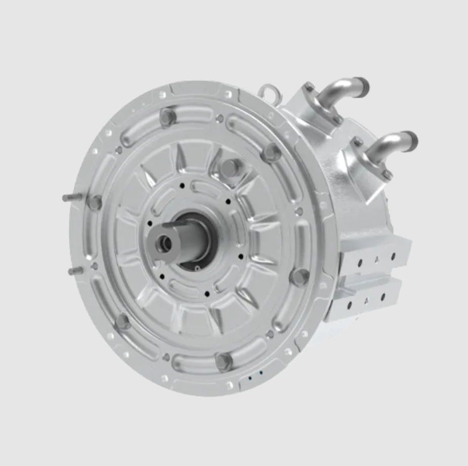
In this work I study a water-cooled interior permanent magnet synchronous motor intended for new-energy vehicle traction. The permanent magnet synchronous motor is a central component of modern electric drive systems because it can provide high efficiency, high power density, and excellent speed-regulation capability. In particular, the interior permanent magnet synchronous motor combines the advantages of a permanent magnet synchronous motor and a reluctance machine, so it can deliver high output torque over a wide speed range while maintaining low back electromotive force at high speed. However, during operation the permanent magnet synchronous motor is subjected to coupled electromagnetic, thermal, and fluid fields. The electromagnetic losses and temperature rise directly affect performance, efficiency, insulation life, and reliability. Therefore, I perform an electromagnetic-thermal coupling numerical analysis of a water-cooled interior permanent magnet synchronous motor and examine the temperature-rise characteristics of key components and the influence of cooling-channel velocity on heat dissipation.
I use a numerical workflow based on a multiphysics platform. First, I establish a three-dimensional model of the permanent magnet synchronous motor. Then I calculate the electromagnetic loss distribution under rated operating conditions. The loss results are imported as heat sources into a thermal-fluid model. Finally, I solve the temperature field and the cooling-water flow field. The main objective is to quantify the temperature distribution in the stator, rotor, permanent magnets, windings, housing, and cooling channel of the interior permanent magnet synchronous motor. I also investigate how the coolant velocity changes the peak temperature and the temperature uniformity along the water channel. The results provide a theoretical basis for thermal management design and efficiency optimization of the permanent magnet synchronous motor.
Physical Model and Assumptions
I consider a three-phase interior permanent magnet synchronous motor with a rated power of 30 kW and a rated speed of 3000 r/min. The motor has eight poles, forty-eight stator slots, an axial Z-shaped cooling channel, and a rotor with embedded permanent magnets. The main geometric parameters are summarized in Table 1. These parameters define the electromagnetic and thermal domains used in my simulations.
| Parameter | Value | Parameter | Value |
|---|---|---|---|
| Rated power | 30 kW | Stator outer diameter | 190 mm |
| Rated speed | 3000 r/min | Stator inner diameter | 125 mm |
| Number of poles | 8 | Rotor outer diameter | 123.8 mm |
| Number of stator slots | 48 | Rotor inner diameter | 74 mm |
| Core length | 110 mm | Permanent magnet thickness | 5.5 mm |
| Air-gap length | 0.6 mm | Permanent magnet width | 16 mm |
The stator winding consists of many copper conductors, insulation layers, and small air regions. A direct geometric representation of every wire and insulation layer would be computationally expensive. Therefore, I use an equivalent homogenized region for the slot winding. The equivalent thermal conductivity is derived from the volume fractions and the thermal conductivities of copper, insulation, and air. If the volume fractions of copper, insulation, and air are denoted by \(\phi_c\), \(\phi_i\), and \(\phi_a\), respectively, then the equivalent thermal conductivity along the slot direction can be approximated by a parallel model:
$$k_{\parallel} = \phi_c k_c + \phi_i k_i + \phi_a k_a$$
For the transverse direction, I use a series model:
$$\frac{1}{k_{\perp}} = \frac{\phi_c}{k_c} + \frac{\phi_i}{k_i} + \frac{\phi_a}{k_a}$$
Here \(k_c\), \(k_i\), and \(k_a\) are the thermal conductivities of copper, insulation, and air. This homogenization allows me to capture the anisotropic heat-transfer behavior of the winding while keeping the mesh size manageable. The permanent magnet synchronous motor model is then meshed in the multiphysics environment. I use fine mesh control in the air gap, stator teeth, winding, permanent magnets, and cooling channel because these regions exhibit large gradients of magnetic flux, loss density, or temperature.
The material properties used in the thermal model are listed in Table 2. The stator and rotor cores are made of silicon steel. The permanent magnets are NdFe30. The housing is aluminum. The shaft is low-carbon steel. The winding is copper, but the slot region is represented by a homogenized anisotropic medium. The air gap is modeled as air. The insulation layer between the winding and the stator core is explicitly included in the equivalent slot model through its low thermal conductivity.
| Component | Material | Density (kg/m³) | Specific heat (J/(kg·K)) | Thermal conductivity (W/(m·K)) |
|---|---|---|---|---|
| Air gap | Air | 1.225 | 1006.43 | 0.0242 |
| Slot insulation | Insulation | 1400 | 1000 | 0.2 |
| Permanent magnet | NdFe30 | 7600 | 420 | 9 |
| Shaft | Low-carbon steel | 7800 | 460 | 60.5 |
| Housing | Aluminum | 2700 | 830 | 168 |
| Iron core | Silicon steel | 7800 | 460 | 30, 30, 0.9384 in stacking direction |
| Coil | Copper | 8954 | 400 | 0.1, 0.1, 174.66 in axial direction |
Electromagnetic Field Formulation
I solve the electromagnetic field of the interior permanent magnet synchronous motor using Maxwell’s equations. The differential and integral forms are summarized in Table 3. These equations govern the magnetic field, electric field, current density, and charge distribution in the permanent magnet synchronous motor. In the low-frequency range relevant to motor operation, the displacement current is usually small, but I retain the full form for completeness.
| Name | Differential form | Integral form |
|---|---|---|
| Ampere’s law | $$\nabla \times \mathbf{H} = \mathbf{J} + \frac{\partial \mathbf{D}}{\partial t}$$ | $$\oint \mathbf{H}\cdot d\mathbf{l} = \int_s \left(\mathbf{J}+\frac{\partial \mathbf{D}}{\partial t}\right)\cdot d\mathbf{s}$$ |
| Faraday’s law | $$\nabla \times \mathbf{E} = -\frac{\partial \mathbf{B}}{\partial t}$$ | $$\oint \mathbf{E}\cdot d\mathbf{l} = -\frac{\partial}{\partial t}\int_s \mathbf{B}\cdot d\mathbf{s}$$ |
| Gauss’s law | $$\nabla \cdot \mathbf{D} = \rho$$ | $$\oint \mathbf{D}\cdot d\mathbf{s} = \int_V \rho\,dv$$ |
| Magnetic flux continuity | $$\nabla \cdot \mathbf{B} = 0$$ | $$\oint \mathbf{B}\cdot d\mathbf{s} = 0$$ |
| Constitutive relations | $$\mathbf{B}=\mu\mathbf{H},\quad \mathbf{D}=\varepsilon\mathbf{E},\quad \mathbf{J}=\sigma\mathbf{E}$$ | Same as differential form |
In Table 3, \(\mathbf{H}\) is the magnetic field intensity, \(\mathbf{B}\) is the magnetic flux density, \(\mathbf{J}\) is the current density, \(\mathbf{D}\) is the electric displacement, \(\mathbf{E}\) is the electric field intensity, \(\rho\) is the volume charge density, \(\mu\) is the permeability, \(\varepsilon\) is the permittivity, and \(\sigma\) is the electrical conductivity. For the permanent magnet synchronous motor, the nonlinear \(B\)-\(H\) curve of silicon steel is used in the stator and rotor cores. The permanent magnets are modeled with a linear recoil permeability and a remanent flux density.
I first perform a static magnetic simulation to obtain the no-load magnetic field distribution of the interior permanent magnet synchronous motor. The magnetic flux lines form closed loops from the north pole to the south pole of adjacent permanent magnets. In the eight-pole permanent magnet synchronous motor, the flux pattern is periodic and symmetric, and eight magnetic circuits are formed. The peak flux density under no-load conditions reaches about 2750 mT. The regions with dense flux lines correspond to high flux density, while the regions with sparse flux lines correspond to low flux density.
After the static magnetic solution, I perform a transient electromagnetic simulation with three-phase alternating current excitation. The core loss is separated into hysteresis loss and eddy-current loss. The solid loss represents the eddy-current loss in large solid conductors under the alternating magnetic field. The total iron loss \(P_{\mathrm{Fe}}\) can be written as:
$$P_{\mathrm{Fe}} = P_h + P_e + P_a$$
where \(P_h\) is the hysteresis loss, \(P_e\) is the classical eddy-current loss, and \(P_a\) is the anomalous loss. For a laminated silicon-steel core, the hysteresis loss is approximately proportional to frequency and the square of flux density:
$$P_h = k_h f B_m^n$$
The eddy-current loss is approximately proportional to the square of frequency and the square of flux density:
$$P_e = k_e f^2 B_m^2$$
The anomalous loss is often expressed as:
$$P_a = k_a f^{1.5} B_m^{1.5}$$
Here \(k_h\), \(k_e\), and \(k_a\) are loss coefficients, \(f\) is the electrical frequency, \(B_m\) is the peak flux density, and \(n\) is the Steinmetz exponent. These loss components are computed in the electromagnetic solver and then mapped to the thermal mesh. The mapping must preserve the spatial distribution of the loss density because the temperature field of the permanent magnet synchronous motor is strongly nonuniform.
Electromagnetic Loss Results
During the transient simulation, the iron loss gradually increases in the initial period and then reaches a stable value. In the stable stage, I obtain an average iron loss of about 267.949 W for the interior permanent magnet synchronous motor. The rotor iron loss is about 20.755 W, and the stator iron loss is about 247.194 W. Therefore, the stator iron loss accounts for about 92.254% of the total iron loss, which makes the stator core the dominant heat source. The eddy-current loss in the large solid conductors is about 19.806 W. These values are summarized in Table 4.
| Loss component | Value (W) | Fraction of total iron loss (%) |
|---|---|---|
| Stator iron loss | 247.194 | 92.254 |
| Rotor iron loss | 20.755 | 7.746 |
| Total iron loss | 267.949 | 100.000 |
| Solid eddy-current loss | 19.806 | Not applicable |
The spatial distribution of the iron loss is nonuniform. The stator teeth and the stator yoke experience high alternating flux density, so their loss density is relatively large. The rotor iron loss is smaller because the rotor rotates synchronously with the fundamental magnetic field, but harmonic fields and slotting effects still produce local eddy currents. The permanent magnets also experience eddy-current loss due to harmonics, although in this study the solid loss in large conductors is reported separately. I use the computed loss density as a volumetric heat source \(q\) in the thermal energy equation. For each region, the local heat generation rate is:
$$q = \frac{P_{\mathrm{loss}}}{V}$$
where \(P_{\mathrm{loss}}\) is the electromagnetic loss in the region and \(V\) is its volume. When the loss is distributed nonuniformly, I map the local loss density from the electromagnetic mesh to the thermal mesh element by element. This step is essential for the accurate prediction of hot spots in the permanent magnet synchronous motor.
Thermal-Fluid Formulation
In the thermal model, I solve the steady-state energy equation in the solid regions and the conjugate heat transfer between the solid and the cooling water. The steady energy equation for a solid with anisotropic thermal conductivity is:
$$\nabla \cdot (\mathbf{k} \nabla T) + q = 0$$
where \(T\) is temperature, \(\mathbf{k}\) is the thermal conductivity tensor, and \(q\) is the volumetric heat source. For the stator winding, the thermal conductivity tensor has different values in the transverse and axial directions because of the layered copper and insulation structure. For the stator and rotor laminations, the stacking direction has a much lower thermal conductivity than the in-plane directions. These anisotropic properties are included in the thermal model of the permanent magnet synchronous motor.
For the cooling water, I solve the continuity equation and the momentum equation:
$$\nabla \cdot \mathbf{u} = 0$$
$$\rho_f (\mathbf{u} \cdot \nabla)\mathbf{u} = -\nabla p + \mu_f \nabla^2 \mathbf{u}$$
Here \(\mathbf{u}\) is the velocity vector, \(\rho_f\) is the fluid density, \(p\) is pressure, and \(\mu_f\) is the dynamic viscosity. The energy equation for the fluid is:
$$\rho_f c_{p,f} \mathbf{u} \cdot \nabla T = \nabla \cdot (k_f \nabla T)$$
where \(c_{p,f}\) is the specific heat of the fluid and \(k_f\) is the fluid thermal conductivity. At the solid-fluid interface, I apply the no-slip condition and the continuity of heat flux:
$$\mathbf{u} = 0$$
$$-k_s \frac{\partial T_s}{\partial n} = -k_f \frac{\partial T_f}{\partial n}$$
The Reynolds number of the cooling channel is defined as:
$$Re = \frac{\rho_f u D_h}{\mu_f}$$
where \(u\) is the mean velocity and \(D_h\) is the hydraulic diameter. For a noncircular channel, the hydraulic diameter is:
$$D_h = \frac{4 A_c}{P_w}$$
where \(A_c\) is the cross-sectional area and \(P_w\) is the wetted perimeter. The local convective heat-transfer coefficient \(h\) is related to the Nusselt number by:
$$Nu = \frac{h D_h}{k_f}$$
For turbulent flow in the cooling channel, I use a standard turbulence model and wall functions. The heat transfer enhancement due to bends and Z-shaped passages is captured by the flow field solution. The pressure drop along the channel is evaluated from the inlet and outlet pressures:
$$\Delta p = p_{\mathrm{in}} – p_{\mathrm{out}}$$
The hydraulic power required to drive the coolant is:
$$P_{\mathrm{pump}} = \Delta p \cdot Q$$
where \(Q\) is the volumetric flow rate. This quantity is important because increasing the coolant velocity can reduce the winding temperature, but it also increases the pump power. Therefore, the thermal management design of the permanent magnet synchronous motor must balance temperature reduction and parasitic power consumption.
Thermal Boundary Conditions and Solution Setup
I apply a velocity-inlet boundary condition at the cooling-channel inlet. The inlet cross-sectional area is 314.159 mm². In the baseline case, the water velocity is 0.65 m/s. The inlet water temperature and the initial temperature of the entire permanent magnet synchronous motor are both 25 °C. I set the outlet boundary as a pressure outlet with a gauge pressure of 0 Pa. The outer surfaces of the housing exchange heat with the ambient air by natural convection and radiation. The convection coefficient on the outer housing is estimated from the ambient conditions. The shaft ends are also allowed to exchange heat with the surroundings. The thermal contact resistance between the housing and the stator core is included as an equivalent thin layer. The insulation layer between the winding and the stator core is modeled explicitly because it strongly affects the heat transfer path from the copper winding to the stator core.
The electromagnetic loss distribution is imported into the thermal model as a volumetric heat source. The stator iron loss is assigned to the stator core, the rotor iron loss is assigned to the rotor core, and the solid eddy-current loss is assigned to the corresponding solid conductor regions. The copper loss in the winding is also included. The total heat generation and the distribution among components determine the temperature field. I use a coupled pressure-velocity solver for the cooling water and a conjugate heat-transfer solver for the solid regions. The convergence criteria are set to \(10^{-6}\) for the energy equation and \(10^{-5}\) for the flow equations. I monitor the maximum temperature in the winding, the permanent magnets, the stator core, the rotor core, the housing, and the cooling water.
Baseline Temperature Distribution
In the baseline case with a coolant velocity of 0.65 m/s, the maximum temperature of the entire permanent magnet synchronous motor occurs at the end region of the stator winding. The peak winding temperature is about 101.5 °C. This hot spot appears because the winding end region has a relatively poor heat-transfer path to the cooling channel and is close to concentrated heat sources. The middle part of the winding is separated from the stator slot by insulation, which reduces the heat transfer from the copper to the stator core. However, the insulation layer also limits the temperature rise of the stator core. The lowest temperature appears in the housing because the cooling channel passes through the housing and removes heat effectively. The rotor core, permanent magnets, and cooling water have relatively narrow temperature spans compared with the winding.
| Component | Minimum temperature (°C) | Maximum temperature (°C) | Temperature span (°C) |
|---|---|---|---|
| Full motor | 24.92 | 101.50 | 76.58 |
| Winding | 37.94 | 101.50 | 63.56 |
| Stator | 33.30 | 55.56 | 22.26 |
| Rotor | 50.87 | 58.63 | 7.76 |
| Permanent magnet | 51.77 | 57.71 | 5.94 |
| Cooling water | 24.92 | 29.02 | 4.10 |
The temperature distribution in the stator winding is highly nonuniform. The end-winding region reaches the highest temperature, while the slot region is cooler because the stator core provides a heat-dissipation path. The insulation layer between the copper and the stator core introduces a thermal resistance, so the winding temperature is higher than the adjacent stator teeth. The stator core temperature is lower than the winding temperature but still shows a noticeable gradient from the teeth to the yoke. The rotor core and permanent magnets are heated by rotor losses and by heat transfer from the stator through the air gap. The air gap has low thermal conductivity, so the rotor and permanent magnets are relatively isolated from the stator. Their temperatures are mostly determined by the rotor loss and the heat transfer along the shaft and through the air gap.
The cooling water temperature increases along the channel because it absorbs heat from the housing and the stator. The water temperature near the inlet is close to 25 °C, and the water temperature near the outlet is about 29 °C in the baseline case. The temperature span of the cooling water is therefore about 4.10 °C. This span is a useful indicator of the heat-removal uniformity. A smaller span means that the water temperature is more uniform and that the local heat transfer is more balanced. The pressure drop along the channel is also important. The inlet pressure is about \(1.734 \times 10^4\) Pa, and the outlet pressure is about \(-4.709 \times 10^2\) Pa. The pressure difference is about \(1.781 \times 10^4\) Pa. The highest flow velocity occurs at the bends, reaching about 2.62 m/s, while the velocity is almost zero in the sharp corner regions. These stagnant regions can cause local hot spots if they are close to high-loss regions.
Effect of Coolant Velocity
I then compare three coolant velocities: 0.65 m/s, 1.0 m/s, and 1.35 m/s. The pressure and velocity distributions show similar trends, but the maximum pressure and maximum velocity increase with the inlet velocity. Higher velocity enhances the convective heat-transfer coefficient and reduces the thermal resistance between the housing and the cooling water. However, the pressure drop also increases, which raises the required pump power. The temperature results for the three cases are summarized in Table 6.
| Component | 0.65 m/s (°C) | 1.0 m/s (°C) | 1.35 m/s (°C) |
|---|---|---|---|
| Full motor | 24.92–101.50 | 24.95–101.40 | 21.88–101.20 |
| Winding | 37.94–101.50 | 36.88–101.40 | 36.02–101.20 |
| Stator | 33.30–55.56 | 32.09–54.70 | 31.23–53.98 |
| Rotor | 50.87–58.63 | 50.38–58.33 | 50.02–58.12 |
| Permanent magnet | 51.77–57.71 | 51.26–57.35 | 50.90–57.10 |
| Cooling water | 24.92–29.02 | 24.95–27.46 | 24.96–26.87 |
As the coolant velocity increases from 0.65 m/s to 1.35 m/s, the maximum winding temperature decreases from 101.50 °C to 101.20 °C, and the minimum winding temperature decreases from 37.94 °C to 36.02 °C. The temperature span of the cooling water decreases from 4.10 °C to 1.91 °C. This means that a higher coolant velocity makes the water temperature more uniform along the channel. The stator temperature also decreases: the maximum stator temperature drops from 55.56 °C to 53.98 °C, and the minimum stator temperature drops from 33.30 °C to 31.23 °C. The rotor and permanent magnet temperatures decrease slightly because they are less directly coupled to the cooling water. The rotor maximum temperature decreases from 58.63 °C to 58.12 °C, and the permanent magnet maximum temperature decreases from 57.71 °C to 57.10 °C. These changes are small compared with the stator and winding changes, but they are still beneficial because permanent magnet temperature affects the magnetic properties and demagnetization risk of the permanent magnet synchronous motor.
The heat-transfer enhancement can be explained by the increase in the convective heat-transfer coefficient. For turbulent flow in a channel, the Nusselt number often follows a correlation of the form:
$$Nu = C Re^m Pr^n$$
where \(C\), \(m\), and \(n\) are empirical constants, and \(Pr\) is the Prandtl number. Since the Reynolds number is proportional to velocity, a higher velocity increases \(Nu\) and therefore increases \(h\). The thermal resistance between the channel wall and the coolant is approximately:
$$R_{\mathrm{conv}} = \frac{1}{h A_s}$$
where \(A_s\) is the wetted area. Increasing \(h\) reduces \(R_{\mathrm{conv}}\), which lowers the wall temperature and the solid temperatures near the channel. However, the pressure drop is approximately proportional to the square of velocity for turbulent flow:
$$\Delta p \propto u^{1.8 \sim 2.0}$$
Therefore, the pump power increases rapidly with velocity:
$$P_{\mathrm{pump}} \propto \Delta p \cdot Q \propto u^{2.8 \sim 3.0}$$
This trade-off is important for the thermal management of the permanent magnet synchronous motor. A moderate increase in velocity can improve temperature uniformity with a relatively small pump-power penalty, but a further increase may produce diminishing thermal benefits and a large hydraulic penalty.
Pressure and Flow Characteristics
The pressure distribution in the cooling channel is strongly influenced by the Z-shaped geometry. The inlet region has the highest pressure, while the outlet region has the lowest pressure. The pressure decreases along the flow path because of friction and local losses at the bends. The local loss coefficient \(K\) for a bend or a sudden change in flow direction is defined by:
$$\Delta p_{\mathrm{local}} = K \frac{1}{2}\rho_f u^2$$
The total pressure drop is the sum of the distributed friction loss and the local losses:
$$\Delta p_{\mathrm{total}} = \sum f_i \frac{L_i}{D_{h,i}} \frac{1}{2}\rho_f u_i^2 + \sum K_j \frac{1}{2}\rho_f u_j^2$$
In the baseline case, the total pressure difference is about \(1.781 \times 10^4\) Pa. The highest local velocity occurs at the bends and reaches about 2.62 m/s. At the sharp corners, however, the velocity approaches zero. These stagnant zones reduce the local heat-transfer coefficient and can cause local temperature peaks if the heat flux is high. Therefore, I recommend rounding the sharp corners or adding flow guides in future designs of the cooling channel for the permanent magnet synchronous motor. Such modifications would reduce the stagnant volume and improve the temperature uniformity without necessarily increasing the flow rate.
| Coolant velocity (m/s) | Maximum pressure (Pa) | Minimum pressure (Pa) | Pressure difference (Pa) | Maximum water temperature (°C) | Water temperature span (°C) |
|---|---|---|---|---|---|
| 0.65 | \(1.734\times10^4\) | \(-4.709\times10^2\) | \(1.781\times10^4\) | 29.02 | 4.10 |
| 1.00 | Higher than baseline | Lower than baseline | Larger than baseline | 27.46 | 2.51 |
| 1.35 | Highest | Lowest | Largest | 26.87 | 1.91 |
Thermal Resistance Network Interpretation
To interpret the results, I construct a simplified thermal resistance network for the permanent magnet synchronous motor. The heat generated in the winding flows through the insulation, the stator core, the housing, and the cooling channel. The heat generated in the rotor and permanent magnets flows through the air gap, the shaft, and the bearings to the housing and the surroundings. The thermal resistance of each path can be written as:
$$R_{\mathrm{cond}} = \frac{L}{k A}$$
for conduction, and
$$R_{\mathrm{conv}} = \frac{1}{h A}$$
for convection. The total thermal resistance from the winding to the coolant is:
$$R_{\mathrm{total}} = R_{\mathrm{Cu-ins}} + R_{\mathrm{ins}} + R_{\mathrm{stator}} + R_{\mathrm{housing}} + R_{\mathrm{conv}} + R_{\mathrm{water}}$$
Because the insulation has a low thermal conductivity, \(R_{\mathrm{ins}}\) is relatively large. This explains why the winding temperature is much higher than the stator core temperature. The cooling water resistance \(R_{\mathrm{conv}}\) decreases as the coolant velocity increases, which reduces the total resistance and lowers the temperature. The stator core resistance is moderate because silicon steel has a high thermal conductivity in the lamination plane but a lower thermal conductivity in the stacking direction. The housing resistance is small because aluminum has a high thermal conductivity. The water resistance includes the thermal resistance due to the finite heat capacity of the water, which is related to the temperature rise of the coolant:
$$T_{\mathrm{out}} – T_{\mathrm{in}} = \frac{P_{\mathrm{heat}}}{\dot{m} c_{p,f}}$$
where \(\dot{m}\) is the mass flow rate. This equation shows that for a given heat load, a higher mass flow rate reduces the water temperature rise. This is consistent with the simulation results: the water temperature span decreases as the coolant velocity increases.
Loss Distribution and Hot-Spot Formation
The electromagnetic loss distribution directly determines the hot-spot locations in the permanent magnet synchronous motor. The stator iron loss is concentrated in the stator teeth and yoke, especially near the air gap where the flux density changes rapidly. The stator winding loss is distributed in the copper conductors, but the end-winding region has a higher temperature because it has less contact with the stator core. The rotor iron loss and permanent magnet eddy-current loss are smaller, but they can still cause local heating in the permanent magnets. The insulation layer between the winding and the stator core limits the heat flow from the copper to the core, so the winding hot spot remains the highest temperature in the machine. The cooling channel in the housing removes heat from the stator and housing, but it has less direct influence on the rotor and permanent magnets. Therefore, the rotor and permanent magnet temperatures are mainly controlled by the rotor loss, the air-gap heat transfer, and the shaft heat conduction.
I also examine the sensitivity of the maximum temperature to the loss distribution. If the total loss is fixed but the stator iron loss fraction increases, the stator temperature increases and the winding temperature may also increase because the stator core is a heat-transfer path for the winding. If the rotor loss increases, the permanent magnet temperature increases, which can reduce the remanent flux density and increase the risk of irreversible demagnetization. Therefore, an accurate prediction of the loss distribution is essential for the thermal design of the permanent magnet synchronous motor. The electromagnetic-thermal coupling approach used here captures this interaction by mapping the loss density from the electromagnetic solution to the thermal solution.
Parametric Influence of Material Properties
The thermal conductivity of the slot insulation has a strong effect on the winding temperature. A lower insulation thermal conductivity increases the thermal resistance between the copper and the stator core, which raises the winding hot-spot temperature. I can express the sensitivity of the winding temperature to the insulation conductivity approximately as:
$$\frac{\partial T_w}{\partial k_{\mathrm{ins}}} < 0$$
This means that increasing the insulation thermal conductivity reduces the winding temperature. In practice, improving the insulation material or reducing the insulation thickness can lower the winding temperature, but the electrical insulation requirements must still be satisfied. The thermal conductivity of the permanent magnet also affects the permanent magnet temperature. A higher magnet thermal conductivity reduces the internal temperature gradient and lowers the peak magnet temperature. The thermal conductivity of the housing material is important because it determines the spreading resistance from the stator to the cooling channel. Aluminum is a good choice because of its high thermal conductivity and low density. The thermal conductivity of the air gap is low, so the air gap acts as a thermal barrier between the stator and the rotor. This is beneficial for limiting the heat flow into the permanent magnets, but it also means that the rotor heat must be removed mainly through the shaft and the end regions.
| Parameter | Effect on winding temperature | Effect on permanent magnet temperature | Design implication |
|---|---|---|---|
| Insulation thermal conductivity | Higher conductivity lowers winding temperature | Small | Use high-conductivity insulation or thinner insulation |
| Coolant velocity | Higher velocity lowers winding temperature | Slightly lowers permanent magnet temperature | Optimize flow rate against pump power |
| Housing thermal conductivity | Higher conductivity lowers stator and winding temperatures | Small | Use aluminum or other high-conductivity material |
| Air-gap thermal conductivity | Small | Higher conductivity increases permanent magnet temperature | Consider air-gap heat transfer in rotor thermal design |
| Stator iron loss | Higher loss raises stator and winding temperatures | Indirect | Reduce harmonic loss by better winding and slot design |
| Rotor loss | Small | Higher loss raises permanent magnet temperature | Reduce rotor harmonics and eddy currents |
Time-Dependent Thermal Behavior
Although the main results are steady-state, I also consider the transient thermal response of the permanent magnet synchronous motor. The transient energy equation for a lumped component is:
$$\rho V c_p \frac{dT}{dt} = P_{\mathrm{loss}} – h A (T – T_\infty)$$
For a step change in loss, the temperature response is:
$$T(t) = T_\infty + (T_0 – T_\infty) e^{-t/\tau}$$
where the thermal time constant is:
$$\tau = \frac{\rho V c_p}{h A}$$
The thermal time constant of the winding is small because the winding has a small mass and a relatively large surface area. The thermal time constant of the rotor and permanent magnets is larger because the rotor is more isolated from the cooling source. This means that the winding temperature responds quickly to changes in load, while the permanent magnet temperature changes more slowly. In a real driving cycle, the permanent magnet synchronous motor experiences repeated acceleration and deceleration, so the thermal response depends on the duty cycle. The electromagnetic-thermal coupling model can be extended to transient conditions to predict the temperature evolution during a driving cycle.
Cooling Channel Design Considerations
The Z-shaped cooling channel provides effective cooling for the housing and stator of the permanent magnet synchronous motor. However, the sharp corners create low-velocity regions. These regions can be improved by using rounded corners, helical channels, or staggered ribs. The local heat-transfer coefficient can be enhanced by increasing turbulence near the wall. A spiral channel or a helical channel can increase the flow path length and the swirl intensity, which improves the heat transfer at the cost of a higher pressure drop. The design of the cooling channel should therefore consider the trade-off among heat-transfer enhancement, pressure drop, and manufacturability. For the permanent magnet synchronous motor studied here, the Z-shaped channel is a reasonable compromise because it provides good cooling with a moderate pressure drop.
I also note that the cooling channel is located in the housing, so it primarily removes heat from the stator and the housing. The rotor and permanent magnets are cooled mainly by the air gap and the shaft. If the permanent magnet temperature becomes a limiting factor, additional cooling measures such as shaft cooling or oil spray cooling may be required. For high-power-density permanent magnet synchronous motor designs, direct cooling of the end winding or the stator core can be more effective than housing cooling alone. The electromagnetic-thermal coupling analysis presented here provides a framework for evaluating such design options.
Comparison of Numerical Methods
The thermal analysis of a permanent magnet synchronous motor can be performed using simplified formulas, equivalent thermal networks, or finite-volume methods. Simplified formulas are fast but cannot resolve local hot spots. Equivalent thermal networks are useful for system-level analysis but have limited spatial resolution. The finite-volume method used here resolves the conjugate heat transfer between the solid and the fluid and captures the local temperature gradients. The electromagnetic-thermal coupling approach combines the accuracy of finite-element electromagnetic analysis with the flexibility of finite-volume thermal-fluid analysis. Table 8 compares these methods for the permanent magnet synchronous motor.
| Method | Advantages | Limitations | Suitability for IPMSM |
|---|---|---|---|
| Simplified formula | Fast, simple | Low accuracy, no local distribution | Initial estimation |
| Equivalent thermal network | Moderate speed, system-level | Limited nodes, approximate | Conceptual design |
| Finite-volume method | High spatial resolution, complex boundaries | Computationally expensive | Detailed thermal design |
| Electromagnetic-thermal coupling | Physically consistent, accurate loss mapping | Requires multiphysics workflow | High-fidelity analysis |
Design Recommendations
Based on my numerical results, I propose several design recommendations for the water-cooled interior permanent magnet synchronous motor. First, the stator winding end region should be given special attention because it is the hottest part of the machine. Improved end-winding impregnation, higher insulation thermal conductivity, and additional end-winding cooling can reduce the peak temperature. Second, the coolant velocity should be selected by considering both thermal performance and pump power. A velocity around 1.0 m/s may provide a good compromise for this permanent magnet synchronous motor because it reduces the water temperature span significantly compared with 0.65 m/s while avoiding the large pressure drop at 1.35 m/s. Third, the cooling channel should be designed to avoid stagnant zones at sharp corners. Rounded corners or flow guides can improve the local heat transfer and reduce the risk of local hot spots. Fourth, the stator iron loss should be reduced by optimizing the stator slot shape, the winding distribution, and the lamination thickness. Since the stator iron loss accounts for about 92.254% of the total iron loss, even a small reduction in stator iron loss can lower the overall temperature. Fifth, the permanent magnet temperature should be monitored because it affects the magnetic performance and demagnetization margin. Although the permanent magnet temperature is lower than the winding temperature in this study, it can increase under high-torque or high-speed conditions.
Uncertainty and Sensitivity
The accuracy of the electromagnetic-thermal coupling analysis depends on several factors. The material properties, especially the thermal contact resistance and the insulation thermal conductivity, have significant uncertainties. The loss coefficients used in the iron-loss model also depend on the manufacturing process and the lamination stacking. The turbulence model and the wall functions introduce some uncertainty in the convective heat-transfer coefficient. To quantify these effects, I could perform a sensitivity analysis using a variance-based method. For a model output \(Y\) and input parameters \(X_i\), the first-order sensitivity index is:
$$S_i = \frac{\mathrm{Var}_{X_i}(\mathbb{E}[Y|X_i])}{\mathrm{Var}(Y)}$$
The total-order sensitivity index is:
$$S_{Ti} = 1 – \frac{\mathrm{Var}_{X_{-i}}(\mathbb{E}[Y|X_{-i}])}{\mathrm{Var}(Y)}$$
Such an analysis would identify the most influential parameters for the winding temperature and the permanent magnet temperature. In the present study, the insulation thermal conductivity and the coolant velocity are expected to be among the most influential parameters. The electromagnetic loss distribution is also important because it determines the heat-source locations. A more detailed uncertainty analysis would require experimental validation, which is beyond the scope of this numerical study.
Conclusion
I have performed an electromagnetic-thermal coupling numerical analysis of a water-cooled interior permanent magnet synchronous motor for new-energy vehicles. I calculated the electromagnetic loss distribution under rated operating conditions and imported the loss density into a thermal-fluid model. I solved the conjugate heat transfer between the solid motor components and the cooling water. The main findings are as follows.
First, the stator winding end region is the highest-temperature location in the permanent magnet synchronous motor. The peak winding temperature is about 101.5 °C in the baseline case. The cooling channel effectively reduces the housing temperature, and the lowest temperature appears in the housing. The rotor, permanent magnets, and cooling water have relatively narrow temperature spans compared with the winding.
Second, the stator iron loss is the dominant heat source. It accounts for about 92.254% of the total iron loss. The rotor iron loss is about 20.755 W, and the stator iron loss is about 247.194 W. The solid eddy-current loss is about 19.806 W. The nonuniform distribution of these losses directly causes the nonuniform temperature field in the interior permanent magnet synchronous motor.
Third, increasing the coolant velocity improves the heat dissipation. As the velocity increases from 0.65 m/s to 1.35 m/s, the maximum winding temperature decreases from 101.50 °C to 101.20 °C, and the cooling-water temperature span decreases from 4.10 °C to 1.91 °C. The stator, rotor, and permanent magnet temperatures also decrease slightly. However, the pressure drop and pump power increase with velocity, so the flow rate should be optimized.
Fourth, the Z-shaped cooling channel creates high-velocity regions at the bends and stagnant regions at the sharp corners. These stagnant regions can reduce the local heat-transfer coefficient and should be avoided by rounding the corners or adding flow guides. The pressure difference in the baseline case is about \(1.781 \times 10^4\) Pa, and the maximum local velocity is about 2.62 m/s.
Fifth, the insulation layer between the winding and the stator core plays a critical role in the winding temperature. A higher insulation thermal conductivity or a thinner insulation layer can reduce the winding hot-spot temperature. The thermal management design of the permanent magnet synchronous motor should therefore consider the insulation material, the cooling-channel geometry, and the electromagnetic loss distribution together.
Overall, the electromagnetic-thermal coupling analysis provides a detailed understanding of the temperature-rise characteristics of the water-cooled interior permanent magnet synchronous motor. The results can be used to optimize the thermal management, improve the efficiency, and extend the service life of the permanent magnet synchronous motor. In future work, I plan to extend the model to transient driving cycles and to validate the numerical results with experimental measurements. I also intend to explore alternative cooling-channel designs and advanced insulation materials to further reduce the hot-spot temperature of the permanent magnet synchronous motor.