
Noise, vibration, and harshness (NVH) is one of the decisive attributes that determines the perceived comfort of a modern new energy vehicle. The traction machine is simultaneously the main source of propulsion and one of the dominant sources of structure-borne and airborne noise in the vehicle. For this reason, the vibration and acoustic behaviour of the PMSM electric motor has a direct influence on the overall NVH fingerprint of the vehicle. Although the absolute sound pressure level radiated by an electrical machine is generally lower than that of a conventional internal combustion engine, the maximum rotational speed of a traction PMSM electric motor can reach several times the speed of a combustion engine. Consequently, the dominant noise frequencies of a PMSM electric motor are shifted towards much higher values, where human hearing is very sensitive and where even modest amplitudes can create a strong subjective discomfort.
In order to evaluate NVH performance during the early design phase, the electromagnetic and structural design of the PMSM electric motor must be assessed jointly, that is, the electromagnetic force must be mapped onto the stator teeth and then used as the excitation of an electromagnetic vibration and acoustic radiation simulation. Because the radiated noise is generated by the structural vibration of the machine, an efficient evaluation during the concept stage can be limited to the electromagnetic vibration response alone. Moreover, during the early design phase the electromagnetic layout usually precedes the detailed structural layout, so there is frequently no complete acoustic radiation surface available. Under such conditions, an electromagnetic vibration simulation is the most practical route for an NVH assessment of the PMSM electric motor.
The operating speed range of a traction PMSM electric motor is extremely wide, and many published studies select the speed points for electromagnetic vibration evaluation using a variety of heuristics. A very common choice is the corner speed of the peak or rated external characteristic curve. However, a careful examination of both bench measurements and vehicle-level NVH data reveals that the corner speed does not necessarily coincide with a stator mode that can couple with the electromagnetic force, and therefore the probability of an NVH problem appearing exactly at the peak or rated corner speed is not high. Other studies perform a full-speed sweep, in which a large number of speed points are analysed. This approach is accurate but suffers from an excessive computational burden, especially when a fine frequency resolution is required across the whole operating envelope of the PMSM electric motor.
In this work I avoid both the brute-force full-speed sweep and the arbitrary peak or rated corner speed selection. Instead, I propose a fast, agile, and targeted electromagnetic vibration simulation methodology that lands directly on the resonant risk speed of the PMSM electric motor. The method first extracts the critical electromagnetic force wave time frequencies and spatial distributions from an analytical electromagnetic vibration mechanism analysis. It then identifies, through a stator structural modal simulation, the mode shapes and natural frequencies that are prone to couple and resonate with the electromagnetic force. Combining the electromagnetic time-space analysis with the stator modal analysis yields the resonant risk speed. At that speed, an electromagnetic force simulation is performed, the force is mapped onto the stator teeth, and the electromagnetic vibration response is computed. Based on the resulting vibration distribution, the stator geometry of the PMSM electric motor is optimised, which effectively mitigates the electromagnetic vibration.
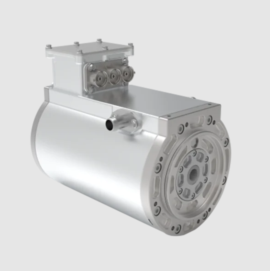
1. Electromagnetic Vibration Mechanism of the PMSM Electric Motor
Because of its high efficiency and high power density, the permanent magnet synchronous machine has become the preferred traction topology for new energy vehicles. When the PMSM electric motor is energised and rotating, the air-gap magnetic field between the stator and the rotor produces a rotating electromagnetic force wave that acts on the stator and excites the corresponding structural modes and vibration deformation. The rotating electromagnetic force wave has two components, a radial component and a tangential component. The radial component is the one that most readily couples with the stator modes and drives a large radial deformation of the stator, and it is therefore the dominant source of electromagnetic vibration. The tangential component produces a secondary tangential vibration and is usually neglected in a first-order assessment. For this reason, the analysis presented here focuses on the radial force as the primary excitation mechanism of the PMSM electric motor.
1.1 Radial electromagnetic force wave
The rotating radial electromagnetic force wave is the principal contributor to the vibration and noise generated by a PMSM electric motor, and it possesses two essential characteristics: a temporal distribution and a spatial distribution. According to the Maxwell stress tensor method, the instantaneous value of the radial electromagnetic force per unit area in the air gap can be expressed as a function of the time variable and the spatial angle:
$$p_{r}(t,\theta)=\frac{b^{2}(t,\theta)}{2\mu_{0}}$$
where the air-gap flux density is itself a function of time and spatial angle, namely the product of the magnetomotive force and the air-gap permeance:
$$b(t,\theta)=f(t,\theta)\,\lambda(t,\theta)$$
In these expressions the symbol denoting the permeability of air appears in the denominator, the magnetomotive force in the air gap is written as a function of time and angle, and the air-gap permeance is likewise expressed as a function of time and angle. For a machine supplied with sinusoidal current and having a pole-pair number equal to a given integer value, the magnetomotive force can be decomposed into a rotor contribution and a stator contribution:
$$f(t,\theta)=\sum_{\mu}f_{\mu}(t,\theta)+\sum_{v}f_{v}(t,\theta)=\sum_{\mu}F_{\mu}\cos(\mu p\theta-\mu\omega t)+\sum_{v}F_{v}\cos(vp\theta-\omega t-\varphi_{v})$$
Here the rotor magnetomotive force harmonics are indexed by one integer order, the stator magnetomotive force harmonics are indexed by a second integer order, the corresponding amplitudes are denoted by the two amplitude symbols, the angular frequency of the fundamental magnetomotive force is denoted by the angular frequency symbol, and the phase angle of the stator harmonic is included explicitly. For an integral-slot machine the stator winding field harmonic orders are given by the arithmetic progression
$$v=6k_{1}+1,\qquad k_{1}=\pm1,\pm2,\pm3,\dots$$
while the rotor field harmonic orders follow the odd-number progression
$$\mu=2k_{2}+1,\qquad k_{2}=0,1,2,3,\dots$$
Substituting the integer indices into the two progressions produces the harmonic content summarised in the following tables.
| Index value | Stator field harmonic order | Typical character |
|---|---|---|
| +1 | 7 | First slot harmonic family |
| −1 | −5 | First slot harmonic family |
| +2 | 13 | Second slot harmonic family |
| −2 | −11 | Second slot harmonic family |
| +3 | 19 | Third slot harmonic family |
| −3 | −17 | Third slot harmonic family |
| Index value | Rotor field harmonic order | Typical character |
|---|---|---|
| 0 | 1 | Fundamental |
| 1 | 3 | Low-order harmonic |
| 2 | 5 | Low-order harmonic |
| 3 | 7 | Low-order harmonic |
| 4 | 9 | Medium-order harmonic |
| 5 | 11 | Medium-order harmonic |
| 6 | 13 | Medium-order harmonic |
| 7 | 15 | Medium-order harmonic |
| 8 | 17 | High-order harmonic |
| 9 | 19 | High-order harmonic |
For an air gap that is uniform in the average sense but slotted at the stator side, the permeance function of the PMSM electric motor can be written as a constant term plus a series of slotting harmonics:
$$\lambda(t,\theta)=\lambda_{0}+\sum_{k=1,2,3}^{\infty}\lambda_{k}\cos(kz\theta)$$
where the constant term represents the mean permeance, the harmonic amplitude represents the slotting modulation depth, the slot number of the stator is denoted by the appropriate symbol, and the index runs over the permeance harmonic orders. Inserting the flux density expression and the permeance expression into the Maxwell stress expression and expanding the product yields the radial force wave in the compact form
$$p_{r}=\frac{1}{2\mu_{0}}\sum_{\mu}\sum_{v}\sum_{k}B\cos\left[(\mu\pm v)p\theta-(\mu\pm1)\omega t\right]$$
The spatial distribution of the radial force wave is described by the force wave order, which is obtained from the combination of the rotor and stator harmonic orders:
$$r=(\mu+v)p \qquad \text{or} \qquad r=(\mu-v)p$$
and the corresponding temporal frequency of the force wave is
$$f_{r}=(\mu+1)f \qquad \text{or} \qquad f_{r}=(\mu-1)f$$
where the symbol for the electrical frequency refers to the fundamental electrical frequency of the PMSM electric motor. For a machine with eight poles and forty-eight slots, the electrical frequency corresponds to four electrical cycles per mechanical revolution, so that a force wave at six times the electrical frequency appears at twenty-four mechanical orders, a force wave at twelve times the electrical frequency appears at forty-eight mechanical orders, and a force wave at twenty-four times the electrical frequency appears at ninety-six mechanical orders.
From the harmonic progressions and the order relation it follows that the electromagnetic radial force waves of an integral-slot PMSM electric motor have orders that are either zero or integer multiples of the pole number. For the eight-pole, forty-eight-slot configuration considered here, the radial force orders are therefore zero, eight, and sixteen. The lower the force wave order, the larger the stator deformation and the resulting electromagnetic vibration, so the zero-order force wave is by far the most dangerous excitation for the PMSM electric motor. Combining the order relation with the frequency relation shows that the zero-order force wave contains frequency components at six, twelve, and twenty-four times the electrical frequency, which originate from the fifth and seventh field harmonics, the eleventh and thirteenth field harmonics, and the seventeenth and nineteenth field harmonics, respectively.
| Rotor harmonic | Stator harmonic | Resulting force order | Multiple of electrical frequency | Mechanical order |
|---|---|---|---|---|
| 5 | −5 | 0 | 6 | 24 |
| 7 | 7 | 0 | 6 | 24 |
| 11 | −11 | 0 | 12 | 48 |
| 13 | 13 | 0 | 12 | 48 |
| 17 | −17 | 0 | 18 | 72 |
| 19 | 19 | 0 | 18 | 72 |
| 23 | −23 | 0 | 24 | 96 |
| 1 | 7 | 8 or 16 | 2 | 8 |
| 1 | −5 | 8 or 16 | 2 | 8 |
1.2 Modal formulation of the stator structure
The electromagnetic vibration of the PMSM electric motor is produced mainly by the electromagnetic radial force exciting the stator modes. For modal analysis, the machine structure can be treated as a vibrating system with multiple degrees of freedom. If the number of degrees of freedom of the system is denoted by a positive integer, the second-order vibration differential equation can be written in the general matrix form
$$M\ddot{X}+C\dot{X}+KX=F(t)$$
where the mass matrix, the damping matrix, the stiffness matrix, the displacement vector, and the excitation force vector appear in the usual order. Damping is normally obtained from modal testing rather than from simulation, and therefore the damping influence is neglected in a purely numerical modal analysis. Furthermore, a free modal analysis ignores the influence of boundary conditions and reveals the general behaviour of the vibrating system. For an undamped free vibration the equation reduces to
$$M\ddot{X}+KX=0$$
A particular solution in vector form is expressed as a modal vector multiplied by a complex exponential in time, and substituting this trial solution leads to the eigenvalue problem
$$(K-\omega_{0}^{2}M)\phi_{i}=0$$
The condition for a non-trivial solution is that the determinant of the dynamic stiffness matrix vanishes:
$$\left|K-\omega_{0}^{2}M\right|=0$$
Solving this characteristic equation yields the eigenvalues, which are the natural frequencies of the individual modes, together with the corresponding eigenvectors, which are the mode shapes of the PMSM electric motor stator structure.
Using a structural finite element solver, I assigned the laminated steel material properties to the stator structure of the PMSM electric motor. The mass density was set to a value of seven thousand six hundred and fifty kilograms per cubic metre, the Poisson ratio was set to zero point two seven, and the elastic modulus was set to one point six five times ten to the eleventh pascal. The resulting free modal analysis produced the mode shapes and natural frequencies listed in the table below.
| Mode description | Mode order | Natural frequency (Hz) | Relevance to electromagnetic excitation |
|---|---|---|---|
| Elliptical deformation | 2 | 754.52 | Couples with second-order force waves |
| Square-like deformation | 4 | 3624.70 | Couples with fourth-order force waves |
| Breathing deformation | 0 | 6706.80 | Couples with zero-order force waves |
Because the low-order modes share a common phase and concentrate a large amount of vibrational energy, they are capable of producing a much larger electromagnetic vibration than the higher-order modes. The breathing mode of order zero is therefore the mode that requires the closest attention in the NVH design of the PMSM electric motor.
1.3 Resonance condition of the PMSM electric motor
Whenever the temporal frequency and the spatial distribution of an electromagnetic force wave coincide with those of a stator mode, a strong resonance occurs. In particular, the zero-order force wave, being a low-order wave, readily resonates with the zero-order breathing mode of the stator, and the resulting amplitude is far larger than that produced by a high-order force wave interacting with a matching high-order stator mode.
According to the origin of the radial force wave, the zero-order spatial force wave possesses temporal components at six, twelve, and twenty-four times the electrical frequency. Considering the maximum rotational speed of the PMSM electric motor, the twenty-four mechanical order component never reaches the breathing mode frequency in the normal operating range, and therefore it cannot generate resonance. The ninety-six mechanical order component can in principle reach the breathing mode, but it arises from the seventeenth and nineteenth field harmonics and is therefore weak in energy, so it does not excite a large resonant response. Consequently, the dominant electromagnetic vibration of the PMSM electric motor is produced by the forty-eight mechanical order component resonating with the zero-order breathing mode of the stator.
2. Electromagnetic Vibration Simulation Workflow
On the basis of the radial force wave analysis, the stator modal analysis, and the electromagnetic resonance mechanism described above, I propose a fast and efficient electromagnetic vibration simulation methodology that targets the resonant risk point directly. The workflow consists of the following steps.
First, the critical electromagnetic force wave time frequencies and spatial distributions are obtained from the electromagnetic vibration mechanism analysis. This step identifies the mechanical orders that can produce a zero-order or otherwise low-order force wave, together with the harmonic families from which they originate.
Second, the stator structural modal simulation provides the mode shapes and natural frequencies that are prone to couple and resonate with the electromagnetic force. The modal analysis is performed on a free stator so that the boundary conditions of the test bench or the vehicle do not mask the intrinsic behaviour of the PMSM electric motor.
Third, the resonant risk speed is computed by matching the modal frequency of interest with the mechanical order of the relevant force wave component. Using the zero-order breathing mode frequency of six thousand seven hundred and six point eight hertz as the reference and the forty-eight mechanical order as the matching excitation, the resonant risk speed is obtained from
$$n_{\text{res}}=\frac{f_{\text{mode}}\times 60}{m}$$
where the modal frequency is expressed in hertz, the mechanical order of the excitation is denoted by the order symbol, and the factor of sixty converts revolutions per second into revolutions per minute. Substituting the numbers gives
$$n_{\text{res}}=\frac{6706.8\times 60}{48}=8383.5\ \text{r/min}$$
It is worth emphasising that this speed point is neither the peak nor the rated corner speed of the external characteristic, nor is it an integer multiple of one hundred or five hundred revolutions per minute. A conventional heuristic based on the corner speed would therefore completely miss this critical operating point of the PMSM electric motor.
Fourth, at the resonant risk speed of eight thousand three hundred and eighty-three point five revolutions per minute and under the corresponding external characteristic operating condition, an electromagnetic force simulation is performed and the resulting force is mapped onto the stator teeth of the PMSM electric motor. The peak instantaneous value of the mapped electromagnetic force is one point six three newtons. Using the mode superposition method, the electromagnetic vibration response is then computed, and the maximum vibration displacement amplitude reaches zero point zero three four nine millimetres. Because damping is not included in the calculation, this value is conservative and slightly larger than the physical response, but it is perfectly suitable as a relative indicator for comparing alternative design proposals of the PMSM electric motor.
The mode superposition formulation used to obtain the harmonic response of the stator structure is expressed as a sum over the participating modes:
$$X(\omega)=\sum_{i=1}^{n}\frac{\phi_{i}\phi_{i}^{T}F(\omega)}{-\omega^{2}m_{i}+j\omega c_{i}+k_{i}}$$
where the modal vector, the modal mass, the modal damping, and the modal stiffness of the individual modes appear explicitly, and the excitation vector is evaluated at the frequency of interest.
| Step | Input | Output | Purpose in the PMSM electric motor workflow |
|---|---|---|---|
| Mechanism analysis | Pole number, slot number, harmonic progressions | Critical force orders and mechanical orders | Filter the excitation space before simulation |
| Modal analysis | Stator geometry, laminated steel properties | Mode shapes and natural frequencies | Identify the modes that can resonate |
| Order matching | Modal frequency, mechanical order | Resonant risk speed | Avoid a blind full-speed sweep |
| Force simulation | Resonant speed, current, control angle | Mapped tooth force | Provide a realistic excitation |
| Vibration simulation | Mapped force, stator modes | Displacement field | Quantify the vibration severity |
| Geometry optimisation | Displacement field, geometry parameters | Revised stator dimensions | Reduce the electromagnetic vibration |
3. Vibration Response and Design Optimisation of the PMSM Electric Motor
Examining the electromagnetic vibration displacement field revealed that a large portion of the stator teeth and the stator yoke exhibited high displacement magnitudes. This indicates that the stator teeth act as the direct carrier of the electromagnetic force, generating a substantial vibration deformation and transmitting that deformation into the yoke. From the perspective of increasing the capability of the stator to carry the electromagnetic force, the geometry of the tooth region and of the yoke region can therefore be optimised. In particular, the yoke thickness and the tooth width should be increased moderately, while the tooth height should be reduced moderately. This combination makes the yoke thicker and the teeth more robust, which raises the load-carrying capability and the structural stiffness of the stator of the PMSM electric motor.
After the geometry modification, the stator structure was again subjected to a modal simulation. The revised design exhibited a significant improvement in both the modal frequencies and the structural stiffness, as summarised in the following table.
| Mode description | Mode order | Baseline frequency (Hz) | Optimised frequency (Hz) | Frequency increase (Hz) |
|---|---|---|---|---|
| Elliptical deformation | 2 | 754.52 | 827.87 | 73.35 |
| Square-like deformation | 4 | 3624.70 | 3990.00 | 365.30 |
| Breathing deformation | 0 | 6706.80 | 7900.20 | 1193.40 |
For the comparison of alternative designs, the influence of damping can be neglected, and therefore the same electromagnetic force was mapped onto the optimised stator modal basis and the electromagnetic vibration displacement was recomputed using the mode superposition method. The maximum vibration displacement amplitude of the optimised design is zero point zero two seven one millimetres, compared with zero point zero three four nine millimetres for the baseline design. This corresponds to a reduction to seventy-seven point six percent of the original value, which confirms that the geometric optimisation is effective in mitigating the electromagnetic vibration of the PMSM electric motor.
| Quantity | Baseline design | Optimised design | Change |
|---|---|---|---|
| Zero-order breathing mode frequency | 6706.8 Hz | 7900.2 Hz | +1193.4 Hz |
| Resonant risk speed at 48 mechanical order | 8383.5 r/min | 9875.3 r/min | Shifted outside the critical band |
| Peak mapped tooth force | 1.63 N | 1.63 N | Unchanged excitation |
| Maximum vibration displacement | 0.0349 mm | 0.0271 mm | −22.4 percent |
| Relative displacement | 100 percent | 77.6 percent | −22.4 percent |
It is instructive to note that the resonant risk speed of the optimised PMSM electric motor is pushed upwards by the stiffening of the stator. The new breathing mode frequency of seven thousand nine hundred point two hertz corresponds to a resonant speed of approximately nine thousand eight hundred and seventy-five revolutions per minute, which lies outside the critical operating band of the baseline machine. In this way the optimisation does not merely reduce the amplitude at a single speed point but relocates the resonance away from the frequently used region of the operating envelope of the PMSM electric motor.
4. Discussion
The methodology described in this work differs from conventional approaches in several important respects. A full-speed sweep evaluates many speed points and provides a complete picture, but it is computationally expensive and often unnecessary when the excitation content of the PMSM electric motor is dominated by a small number of force wave orders. A corner-speed evaluation is computationally cheap but is not physically justified, because the corner speed is determined by the flux-weakening transition rather than by the modal properties of the stator of the PMSM electric motor. The order-matching approach adopted here combines the physical rigour of the full-speed method with the efficiency of a single-point evaluation.
The key enabling insight is that the electromagnetic force spectrum of an integral-slot PMSM electric motor is discrete. The force waves appear only at specific combinations of spatial order and temporal frequency, and the low-order waves are the ones that can produce a significant vibration. Once the spatial order and the temporal frequency of the dominant wave are known, the resonant speed follows directly from the stator modal frequency. This reduces the search space from a continuum of operating points to a small number of candidate speeds.
| Evaluation strategy | Number of simulated speed points | Physical justification | Computational cost | Suitability for early design |
|---|---|---|---|---|
| Corner speed only | One | Weak | Very low | Poor, risks missing the resonance |
| Full-speed sweep | Many | Strong | Very high | Impractical for iterative design |
| Order matching | Few | Strong | Low | Excellent for the PMSM electric motor |
| Hybrid modal screening | Few plus screening | Strong | Moderate | Good for multi-objective optimisation |
The optimisation of the stator geometry also illustrates a general principle for the NVH design of a PMSM electric motor. Because the electromagnetic force is essentially determined by the electromagnetic topology and the current waveform, the most direct way to reduce the vibration response without degrading the torque capability is to increase the structural stiffness of the stator. Increasing the yoke thickness raises the bending stiffness of the stator ring, increasing the tooth width raises the local stiffness of the tooth root, and reducing the tooth height lowers the bending compliance of the tooth. Together these changes raise the natural frequency of the breathing mode and reduce the vibration amplitude at the original resonant speed.
An additional consideration is that the optimisation of the stator geometry of the PMSM electric motor inevitably interacts with the electromagnetic design. Increasing the yoke thickness reduces the available slot area for a given outer diameter, and increasing the tooth width reduces the slot width. Both effects tend to reduce the copper fill factor and can therefore reduce the torque density. A complete optimisation study should therefore treat the electromagnetic and structural objectives simultaneously, for example by means of a multi-objective optimisation in which the vibration displacement and the torque density are evaluated together.
5. Practical Guidelines for the PMSM Electric Motor Design Process
Based on the analysis presented above, the following practical guidelines can be formulated for the NVH-oriented design of a PMSM electric motor.
The first guideline is to perform the order matching before any detailed vibration simulation is attempted. The spatial order and temporal frequency of the dominant electromagnetic force wave should be derived analytically from the pole number and the slot number of the PMSM electric motor. For an integral-slot machine the low-order waves are always associated with the low-order harmonic families, and the corresponding mechanical orders can be tabulated in advance for any candidate pole and slot combination.
The second guideline is to perform the free modal analysis of the stator early. The breathing mode frequency is the single most important structural parameter for the electromagnetic vibration of the PMSM electric motor, because the breathing mode couples with the zero-order force wave and produces the largest deformation. The modal frequency should be compared with the excitation order that can realistically be reached within the operating speed range.
The third guideline is to compute the resonant risk speed explicitly. The speed at which the mode frequency equals the product of the mechanical order and the rotational frequency is the speed that deserves the closest attention. Any evaluation that ignores this speed, however convenient it may be, risks missing the worst-case operating point of the PMSM electric motor.
The fourth guideline is to use a consistent post-processing metric when comparing alternative designs. Because damping is difficult to measure at the concept stage, the undamped displacement computed from the mode superposition method is a conservative but consistent indicator. The relative ranking of alternative stator geometries is preserved even when the absolute amplitude is overestimated.
| Design stage | Primary action | Critical parameter | Expected benefit |
|---|---|---|---|
| Topology selection | Choose pole and slot combination | Force wave order | Avoid low-order zero-order waves if possible |
| Electromagnetic layout | Shape the magnetomotive force spectrum | Harmonic amplitude | Reduce the source of the excitation |
| Structural layout | Size the yoke and the teeth | Breathing mode frequency | Shift the resonance away from the operating range |
| Verification | Map the force and solve the response | Peak displacement | Confirm the vibration margin |
| Optimisation | Iterate the geometry | Torque density and vibration | Balance the electromagnetic and NVH objectives |
6. Conclusion
I have presented a fast, efficient, and physically targeted electromagnetic vibration simulation methodology for traction PMSM electric motor design. The method proceeds from an analytical electromagnetic vibration mechanism analysis that identifies the critical force wave time frequencies and spatial distributions, through a stator structural modal simulation that identifies the mode shapes and natural frequencies prone to resonance, to an order-matching calculation that yields the resonant risk speed directly. At that speed an electromagnetic force simulation is performed, the force is mapped onto the stator teeth, and the electromagnetic vibration response is computed. The resulting vibration field is then used to guide a geometric optimisation of the stator, in which the yoke thickness and the tooth width are increased moderately and the tooth height is reduced moderately.
For the eight-pole, forty-eight-slot configuration considered here, the dominant excitation was identified as the zero-order force wave at forty-eight mechanical orders, arising from the eleventh and thirteenth field harmonics. Matching this excitation with the zero-order breathing mode of the baseline stator gave a resonant risk speed of eight thousand three hundred and eighty-three point five revolutions per minute, a speed that would not have been selected by any corner-speed heuristic. At this speed the peak mapped electromagnetic force was one point six three newtons and the maximum undamped vibration displacement was zero point zero three four nine millimetres. After the geometric optimisation, the breathing mode frequency rose from six thousand seven hundred and six point eight hertz to seven thousand nine hundred point two hertz, and the maximum displacement fell to zero point zero two seven one millimetres, which is seventy-seven point six percent of the baseline value. This represents a substantial mitigation of the electromagnetic vibration of the PMSM electric motor and confirms the effectiveness of the proposed workflow.
The broader significance of the approach is that it replaces an expensive parametric sweep with a small number of physically justified simulation points. Because the excitation spectrum of a PMSM electric motor is discrete, the resonant interaction between the electromagnetic force and the stator structure is confined to a limited set of speed and frequency combinations. Identifying those combinations analytically before any numerical simulation makes the NVH evaluation fast enough to be embedded in an iterative design loop, while remaining faithful to the underlying physics of the electromagnetic vibration of the PMSM electric motor.
| Parameter | Symbolic description | Baseline value | Optimised value |
|---|---|---|---|
| Pole number | Pole count of the PMSM electric motor | 8 | 8 |
| Slot number | Stator slot count | 48 | 48 |
| Dominant force order | Spatial order of the critical wave | 0 | 0 |
| Dominant mechanical order | Mechanical order of the critical wave | 48 | 48 |
| Breathing mode frequency | Zero-order natural frequency | 6706.8 Hz | 7900.2 Hz |
| Resonant risk speed | Speed of the order match | 8383.5 r/min | 9875.3 r/min |
| Peak tooth force | Mapped electromagnetic force | 1.63 N | 1.63 N |
| Peak displacement | Maximum vibration amplitude | 0.0349 mm | 0.0271 mm |
The methodology is general and can be applied to any integral-slot PMSM electric motor once the pole and slot numbers, the stator material properties, and the operating speed range are known. Future work should extend the approach to fractional-slot concentrated-winding topologies, where the force wave spectrum contains additional low-order components that are not captured by the integral-slot progressions used here, and to the inclusion of measured damping values so that absolute rather than relative vibration amplitudes can be predicted for the PMSM electric motor.