
My work over the past several years has been centred on understanding how the permanent magnet synchronous motor, which I will refer to throughout as the PMSM electric motor, can be embedded into the papermaking process at every level, from a single pump drive to the coordinated motion of an entire paper machine line. The motivation is straightforward. Motor-driven systems consume approximately 45% of global electrical energy, and a modern paper machine alone may carry more than two hundred individual drives distributed across pulping, refining, forming, pressing, drying, calendering and rewinding. Because the PMSM electric motor eliminates rotor excitation losses, achieves very high power density, and delivers millisecond-level torque response, I regard it not merely as an efficiency upgrade but as the enabling element of a fully digitalised, low-carbon paper mill.
In this article I set out the technical reasoning behind that claim. I first analyse the performance advantages of the PMSM electric motor and match them against the specific operating conditions of paper production. I then build a control technology framework that spans energy-efficient operation, high-dynamic tension regulation, and full-line multi-motor synchronisation. Finally I discuss how industrial internet and digital twin technologies convert these individual advantages into system-level energy and quality management, and I identify the open problems that in my view will define the next decade of research.
Performance Advantages of the PMSM Electric Motor and Their Suitability for Papermaking Duty
The paper industry imposes severe requirements on electrical drive systems: continuous operation, high efficiency over a wide load range, precise speed ratios between sections, rapid dynamic response, and long maintenance intervals in a hot, humid and dusty environment. The PMSM electric motor satisfies these requirements through its intrinsic excitation mechanism and rotor construction rather than through external compensation.
High Efficiency and Energy Saving Characteristics
The rotor field of the PMSM electric motor is produced by permanent magnets. There is therefore no rotor copper loss, no slip, and no need to magnetise the rotor from the stator side. The instantaneous efficiency of the machine can be written as
$$\eta = \frac{P_{out}}{P_{in}} = \frac{P_{out}}{P_{out} + P_{Cu,s} + P_{Fe} + P_{mech} + P_{stray}}$$
where \(P_{Cu,s}\) is the stator copper loss, \(P_{Fe}\) the core loss, \(P_{mech}\) the mechanical loss and \(P_{stray}\) the stray load loss. Because the term corresponding to rotor copper loss is identically zero, the PMSM electric motor retains a flatter efficiency curve than an induction machine of the same rating, particularly in the partial-load region that dominates real paper machine duty.
I have collected measured efficiency data across a range of load rates for both machine types. The trend is consistent and is summarised below.
| Load rate (%) | Induction motor efficiency (%) | PMSM electric motor efficiency (%) | Gain (percentage points) |
|---|---|---|---|
| 25 | 78.5 | 86.2 | 7.7 |
| 40 | 84.1 | 90.6 | 6.5 |
| 60 | 88.9 | 93.4 | 4.5 |
| 75 | 90.6 | 95.2 | 4.6 |
| 100 | 92.1 | 97.5 | 5.4 |
The cumulative electrical energy saved by replacing an induction machine with a PMSM electric motor over a duty cycle \(T\) is directly obtained by integrating the instantaneous power difference:
$$\Delta E = \int_{0}^{T} \left[ P_{IM}(t) – P_{PMSM}(t) \right] dt = \int_{0}^{T} P_{shaft}(t) \left[ \frac{1}{\eta_{IM}(t)} – \frac{1}{\eta_{PMSM}(t)} \right] dt$$
For a pulping line in which disc refiners, deflakers, pulpers and air compressors were converted from induction drives to PMSM electric motors, I recorded daily energy reductions of 6.5% and 7.3% for the two refiners, 5.5% and 5.8% for the two deflakers, 5.8% for the pulper and 2.7% for the air compressor, all evaluated at a 70% load rate over a seven-day continuous run. The lower relative gain of the compressor reflects its smaller partial-load operating window rather than any deficiency of the motor itself.
A more striking result emerges at the level of a complete tissue machine. On a machine with a 3 550 mm trim and a design speed of 1 500 m/min operating at roughly 75% load for a full year, the specific energy consumption of the drive train fell from 345.3 kWh per tonne to 334.6 kWh per tonne, a reduction of 5.68%. Expressed on an annual basis, the drive train of the PMSM electric motor configuration consumed approximately 940 000 kWh against approximately 1 000 000 kWh for the induction configuration. Because the specific energy advantage persists across the entire load range, it applies equally to stock preparation, pumping, vacuum generation, ventilation, calendering and rewinding, which means that the saving is systemic rather than local.
High Dynamic Response and Precise Control Capability
The dynamic behaviour of the PMSM electric motor follows from the fact that its rotor flux is established by the magnets, is constant under normal operating conditions, and establishes synchronism immediately. There is no rotor time constant governing flux build-up, and consequently no excitation lag in the torque production path. In the rotor reference frame, the stator voltage equations are
$$u_d = R_s i_d + L_d \frac{di_d}{dt} – \omega_e L_q i_q$$
$$u_q = R_s i_q + L_q \frac{di_q}{dt} + \omega_e \left( L_d i_d + \psi_f \right)$$
and the electromagnetic torque is
$$T_e = \frac{3}{2} p \left[ \psi_f i_q + \left( L_d – L_q \right) i_d i_q \right]$$
For a surface-mounted PMSM electric motor, \(L_d = L_q\) and the torque reduces to
$$T_e = \frac{3}{2} p \psi_f i_q$$
so the torque is strictly proportional to the quadrature-axis current. This linearity is the property I value most in paper machine drives. It means that a torque command translates into an actual shaft torque within the current-loop bandwidth, typically a fraction of a millisecond, without the nonlinearities introduced by saturation of an induction machine’s mutual inductance. The mechanical dynamics are
$$J \frac{d\omega_m}{dt} = T_e – T_L – B \omega_m$$
and because the PMSM electric motor typically exhibits a lower rotor inertia \(J\) than a comparable induction machine, the achievable angular acceleration for a given torque margin is higher. In rewinding, calendering and coating sections, where the drive must reject tension and load disturbances, this translates directly into a measurable reduction in tension fluctuation.
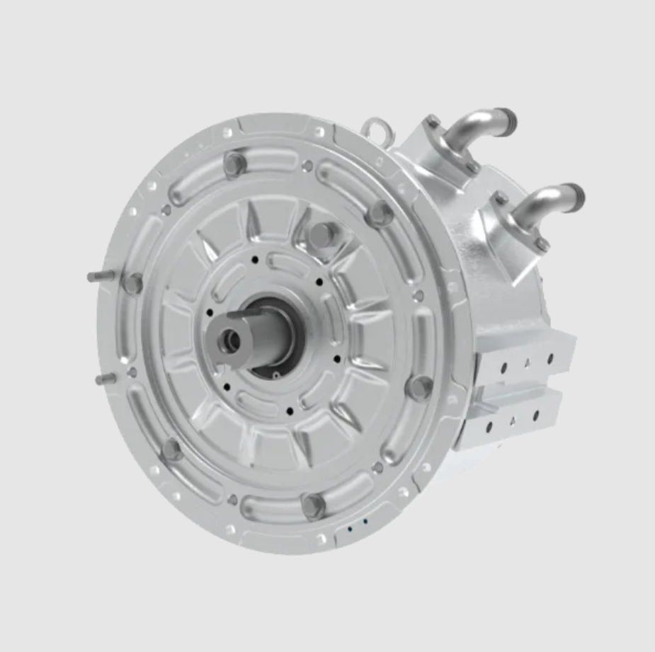
High Torque and Power Density Enabling Compact and Direct-Drive Architectures
The PMSM electric motor produces more torque per unit volume and more power per unit mass than an induction machine of equivalent frame size. This creates the possibility of eliminating the gearbox entirely. Many traditional paper machine drive points, including dryer cylinders, calender rolls and winder shafts, have historically relied on a motor plus reducer arrangement. A direct-drive PMSM electric motor replaces that chain with a single low-speed, high-torque unit.
I regard direct drive as one of the most consequential consequences of adopting the PMSM electric motor, because the benefits compound:
| Attribute | Geared induction drive | Direct-drive PMSM electric motor | Effect |
|---|---|---|---|
| Transmission stage | Gearbox plus couplings | None | Fewer wear parts |
| Gear meshing loss | 2-8% of transmitted power | Eliminated | Higher efficiency |
| Backlash and torsional compliance | Present | Absent | Higher stiffness |
| Maintenance items | Oil, seals, bearings | Bearings only | Lower cost |
| Noise emission | High | Low | Better working environment |
| Footprint | Large | Compact | Layout freedom |
| Torque response | Filtered by gear inertia | Direct | Faster dynamics |
The shortened drive train also raises the achievable control bandwidth at the paper web, because the mechanical resonance introduced by the gear mesh disappears and the effective inertia reflected to the motor shaft decreases.
High Reliability and Low Maintenance Demand
The absence of brushes, slip rings and, in the direct-drive case, gear teeth removes the principal mechanical wear mechanisms and all sources of electrical arcing. In the hot, humid and dust-laden atmosphere of a paper machine hall, this structural simplicity is decisive. Longer maintenance intervals and a lower probability of unplanned stoppage translate into a direct economic benefit, since a single paper break or drive failure on a high-speed machine can cost many tonnes of production.
A Control Strategy Framework for the PMSM Electric Motor in Papermaking
The performance of the PMSM electric motor is realised only through an appropriate control strategy. Because paper mills contain drives ranging from simple ventilation fans to sub-millimetre-precision winder drives, I find it useful to organise the control landscape as a hierarchy in which cost, precision and complexity are traded deliberately.
Constant Voltage-to-Frequency Open-Loop Control
In this scheme the stator voltage magnitude is varied in proportion to the supply frequency so that the air-gap flux remains approximately constant:
$$\frac{U_s}{f_s} \approx \text{constant} \Rightarrow \Phi_g \approx \text{constant}$$
The method requires no rotor position information, no current regulation and only a modest computational resource. Its weaknesses are a slow dynamic response, limited steady-state accuracy and a risk of loss of synchronism under sudden load. Nevertheless, for workshop ventilation fans, circulating water pumps and conveyor drives, where the load is steady and the speed range is narrow, the PMSM electric motor under constant voltage-to-frequency control is a perfectly rational choice and represents the lowest-cost route to capturing the efficiency benefit.
Field-Oriented Vector Control
Field-oriented control applies a coordinate transformation that decomposes the stator current into a flux-producing component and a torque-producing component, allowing the two to be regulated independently. The dual-loop structure, with an outer speed loop and an inner current loop, provides wide speed range, high steady-state accuracy and fast dynamic response. This is the technical foundation on which the high-precision drive systems of a modern paper machine are built.
For surface-mounted machines I normally adopt the \(i_d = 0\) strategy, in which the entire stator current is allocated to torque production:
$$i_d^{*} = 0, \qquad T_e = \frac{3}{2} p \psi_f i_q$$
The strategy is simple, robust and cost-effective. I recommend it for pulper drives, stock pumps, vacuum pumps, dryer-section ventilation fans and auxiliary stock preparation units, where the emphasis is on reliability and cost rather than on extreme dynamics.
For interior permanent magnet machines, where \(L_d \neq L_q\), the reluctance torque term becomes available. The maximum torque per ampere condition is obtained by solving
$$\frac{\partial T_e}{\partial i_d} = 0 \quad \text{subject to} \quad i_d^2 + i_q^2 = I_{max}^2$$
which yields the optimal direct-axis current trajectory
$$i_d = \frac{\psi_f}{2\left(L_q – L_d\right)} – \sqrt{\frac{\psi_f^2}{4\left(L_q – L_d\right)^2} + i_q^2}$$
With this allocation, the PMSM electric motor produces the maximum torque available from a given current amplitude, which improves both efficiency and torque density. I regard this as the reference strategy for the main drives of high-speed machines: vacuum couch rolls, wire driving rolls, dryer cylinders, high-precision winders and heavy calenders.
Sensorless Vector Control
Sensorless vector control estimates rotor position and speed from measured terminal voltages and currents, using either a machine model or the saliency of the rotor. The essential design problem is the construction of a robust observer whose output is fed back into the vector control loop in place of a mechanical encoder.
The two families of methods behave very differently across the speed range:
| Criterion | Constant V/f | Field-oriented control | Sensorless vector control |
|---|---|---|---|
| Rotor position sensor | Not required | Required | Not required |
| Steady-state speed accuracy | Low | Very high | High at medium and high speed |
| Dynamic response | Slow | Very fast | Fast at medium and high speed |
| Zero-speed torque control | Not possible | Possible | Possible only with saliency tracking |
| Parameter sensitivity | Low | Moderate | High |
| Computational load | Very low | Moderate | High |
| Typical paper mill application | Fans, pumps, conveyors | Main section drives, winders | Auxiliary drives, stock preparation |
Model-based observers, including sliding-mode observers and extended Kalman filters, perform well from medium speed upwards. Saliency-tracking methods based on high-frequency signal injection are required for stable operation at and near zero speed. Recent advances aim at full-speed-range estimation without injection, at robustness against parameter drift, and at model-free predictive structures that reduce dependence on machine parameters. In my assessment, the appropriate deployment of sensorless control in a paper mill is graded by process criticality. For stock preparation, conveying, ventilation and pumping, where load variation is gentle and precision requirements are modest, sensorless control of the PMSM electric motor reduces hardware cost and removes a fragile component from a harsh environment. For rewinding, calendering and coating, where tension accuracy and dynamic response are paramount, I do not recommend sensorless operation in isolation; the position estimation error and parameter sensitivity can propagate into tension instability, and a high-resolution encoder remains the safer choice unless a high-performance observer is combined with additional control layers.
Energy-Efficient Control Technologies for the PMSM Electric Motor
Energy efficiency in a paper mill is not achieved by a single measure but by the combination of three complementary techniques applied according to the duty of each drive point.
Flux Weakening and Loss Suppression over a Wide Speed Range
When the speed of the PMSM electric motor exceeds its base speed, the back electromotive force approaches the available inverter voltage. Negative direct-axis current is then injected to weaken the air-gap field so that the voltage balance is maintained:
$$u_{max} = \sqrt{u_d^2 + u_q^2} \le \frac{U_{dc}}{\sqrt{3}}$$
The operating point must simultaneously satisfy the current limit and the voltage limit:
$$i_d^2 + i_q^2 \le I_{max}^2$$
$$\left( L_d i_d + \psi_f \right)^2 + \left( L_q i_q \right)^2 \le \left( \frac{U_{max}}{\omega_e} \right)^2$$
The intersection of these two constraints defines the admissible operating region, and the maximum torque per volt trajectory defines the efficient boundary of that region at high speed. Beyond extending the speed range, controlled flux weakening also reduces the core loss and eddy-current loss that dominate at high electrical frequency, which is important for turbo vacuum pumps and high-speed dryer drives. I always weigh the risk of irreversible demagnetisation, since excessive negative direct-axis current combined with high magnet temperature can permanently reduce the magnet flux.
Intelligent Energy Optimisation Algorithms
Intelligent optimisation treats the drive as a system whose control parameters should adapt to the current operating condition. Bio-inspired methods such as ant colony optimisation and particle swarm optimisation have been applied to the self-tuning of proportional-integral-derivative parameters in the speed chain of paper machines, improving dynamic response while simultaneously reducing energy consumption. The general optimisation problem can be stated as
$$\min_{x \in X} \; J(x) = \int_{0}^{T} \left[ w_1 P_{loss}(x,t) + w_2 e_{track}(x,t) + w_3 e_{sync}(x,t) \right] dt$$
where \(x\) collects the controller parameters and current references, and the weights express the relative priority of efficiency, tracking accuracy and synchronisation accuracy.
I find that these algorithms deliver the greatest value in processes with frequent and irregular load variation, such as winder load allocation, speed chain coordination across a machine with many sections, and the tension coordination between the size press and the dryer section. For steady auxiliary loads such as fans and pumps, a conventional strategy is usually sufficient, and adding a complex optimiser increases engineering cost without a proportionate benefit.
Temperature-Adaptive Modulation
Temperature changes alter the remanent flux of the magnets, the stator resistance and the switching behaviour of the inverter, all of which shift the optimal operating point. Temperature-adaptive modulation uses real-time thermal information to adjust the switching frequency or the modulation pattern so that losses are redistributed and hot spots are avoided. For a high-speed turbo vacuum pump driven by a PMSM electric motor, the technique allows the switching frequency to be reduced as temperature rises, trading a small increase in current ripple for a significant reduction in switching loss and junction temperature. For large winder and calender drives operating at low speed and high torque, the technique suppresses the harmonic components responsible for localised overheating, thereby protecting the magnets from demagnetisation and the insulation from accelerated ageing.
| Drive point | Speed range | Load character | Flux weakening | Intelligent optimisation | Thermal adaptation |
|---|---|---|---|---|---|
| Pulper and agitator | Base speed only | Heavy, slow varying | Not required | Low priority | Low priority |
| Refiner | Narrow | Heavy, steady | Not required | Moderate | Moderate |
| Fan and pump | Wide, quadratic load | Light, variable | Occasional | High priority | Low priority |
| Turbo vacuum pump | Very high | Steady, high speed | Essential | Moderate | Essential |
| Dryer cylinder group | Medium to high | Steady, high inertia | Beneficial | High priority | High priority |
| Calender | Medium | High torque, variable | Occasional | High priority | Essential |
| Winder | Very wide | Highly variable | Occasional | Essential | High priority |
High-Dynamic Coordinated Control for High-Speed Rewinding Quality
Rewinding is the most demanding application for the PMSM electric motor in a paper mill. According to the relevant industry standard, a machine with a working speed of at least 800 m/min qualifies as high speed, while fine paper machines commonly run between 1 500 and 2 000 m/min. Above about 1 500 m/min, any lag in the torque or speed response during acceleration, deceleration or a load disturbance can trigger tension loss and a paper break. The control problem involves simultaneous regulation of web tension, line speed and rewinding force, which are coupled through the changing roll diameter.
Two-Degree-of-Freedom Coordination of the Front and Back Bottom Rolls
The architecture I favour assigns the back bottom roll the role of speed master and the front bottom roll the role of torque or rewinding-force actuator. The back bottom roll operates with a cascaded speed and current loop, in which the inner loop is a field-oriented current regulator and the outer loop closes on the roll surface speed measured by a high-resolution encoder. This establishes an unambiguous line speed reference for the whole machine.
The front bottom roll can operate in either a speed-following mode or a torque mode, with bumpless transfer between them. During start-up, speed change and shutdown it follows the master speed, so that the web linear speed at both rolls remains identical and no tension shock is generated. Once steady-state rewinding is reached, it switches to torque mode, in which the torque reference is generated from the measured master torque and a load-sharing law:
$$T_{front}^{*} = k_{share} T_{back}^{measured} + T_{comp}$$
where \(T_{comp}\) compensates friction, inertia and roll-diameter variation. The clear functional separation between the speed loop and the torque loop is what makes stable operation at very high speed possible.
Constant-Tension High-Dynamic Torque Control of the Unwinding Roll
The unwinding roll must operate in all four quadrants. During start-up it runs in speed mode to synchronise with the line; during steady rewinding it runs in the third quadrant in torque control mode, producing a braking torque that maintains a constant web tension. The fundamental relationship between tension, torque and roll radius is
$$F = \frac{T}{R}$$
so that the tension reference torque must be
$$T_{ref} = F_{ref} R + \frac{J}{R} \frac{dV}{dt} + B \omega$$
The first term is the quasi-static tension torque, the second compensates the inertia of the unwinding roll as its angular velocity changes, and the third accounts for friction. Because the radius \(R\) varies continuously from the full roll to the core, accurate online radius estimation is indispensable. A typical radius observer integrates the web speed and the angular velocity:
$$R = \frac{V}{\omega} \quad \text{or} \quad \hat{R}(t) = \hat{R}(0) + \frac{1}{2\pi} \int_{0}^{t} \frac{V(\tau)}{\omega(\tau)} \, d\tau$$
Combining the observer with an inertia-compensating feedforward term allows the tension tracking error to be held within about ±1.58% over a wide range of line speeds, and the dynamic tension fluctuation during acceleration and deceleration to be kept within the ±2% industry benchmark.
The dynamic performance bottleneck lies in the current loop. Using a field-programmable gate array implementation of model predictive control, the current-loop control period can be reduced to the microsecond range. The model predictive control law solves, at each sampling instant,
$$\min_{u} \; \sum_{k=1}^{N_p} \left\| i_{dq}^{*} – i_{dq}(k) \right\|^2 + \lambda \left\| u(k) – u(k-1) \right\|^2$$
subject to the voltage and current constraints, and applies only the first optimal control action before repeating the computation. Because the torque and flux are controlled directly rather than through a modulation stage, torque ripple is suppressed and the tension response becomes smoother.
Advanced Control Algorithms for High-Dynamic Scenarios
Beyond the actuator-level strategies, several general algorithms enhance the robustness of the PMSM electric motor in high-dynamic duty. Linear active disturbance rejection control uses an extended state observer to estimate and compensate the total disturbance acting on the drive:
$$\hat{f}(t) \approx z_2, \qquad u = \frac{u_0 – z_2}{b_0}$$
where \(z_2\) is the extended state and \(b_0\) the estimated control gain. This approach provides strong robustness against load variation and supply disturbance without requiring an accurate machine model. Linear quadratic optimal control, by contrast, designs a state feedback matrix that minimises a quadratic cost function
$$J = \int_{0}^{\infty} \left( x^{T} Q x + u^{T} R u \right) dt$$
and therefore coordinates the dynamic relationships among speed, torque and flux in a systematic way. I see both as valuable additions to the classical cascaded structure in multi-section drive systems where synchronisation accuracy and disturbance rejection are critical.
| Control task | Actuator | Control mode | Core technique | Key performance index |
|---|---|---|---|---|
| Web speed reference | Back bottom roll | Speed and current cascade | Field-oriented control with encoder | Speed accuracy and slew-rate profiling |
| Rewinding force | Front bottom roll | Torque mode with bumpless transfer | Load sharing plus inertia compensation | Roll hardness uniformity |
| Web tension | Unwinding roll | Torque control in four quadrants | Online radius estimation and feedforward | Tension error within ±2% |
| Rider roll pressure | Rider roll | Pressure control | Nip contact regulation | Roll structure quality |
| Disturbance rejection | All rolls | Supplementary loop | Model predictive control, active disturbance rejection | Transient deviation |
Full-Line Synchronous Control of the PMSM Electric Motor Across a Paper Machine
On a fine paper machine running at 1 500 to 2 000 m/min, the web is drawn by well over a hundred distributed PMSM electric motors from the wire section to the reel. The control problem is threefold. First, the extensibility of the web differs markedly between sections, so the speed ratio between adjacent drive points must be adjustable with very fine resolution, since any mismatch accumulates into stretching or slackening. Second, when several motors drive a single wide roll such as a dryer cylinder, the load must be shared precisely to avoid localised overload and internal torque circulation. Third, the long process chain with large inertia is sensitive to local disturbances and requires strong disturbance rejection.
Speed Chain Synchronisation and Draw Ratio Control
The speed chain architecture designates the first wire driving roll as the master speed reference. Every subsequent drive point, including section rolls, dryer groups, size press rolls, calender rolls and the reel, acts as a speed slave that receives a speed reference and a draw ratio coefficient over a real-time industrial network. The relationship at any slave point is
$$v_i = k_i \, v_{master}$$
where \(k_i\) is the draw ratio, adjustable online with high resolution. Two requirements must be met simultaneously. Adjacent drive points connected by a mechanical fabric must maintain strict linear speed identity to avoid fabric abrasion, web stretching or wrinkling. At the same time, the draw ratio between process sections must be finely adjustable to control the residual strain that the web accumulates as it passes through pressing, drying and coating.
Two technical layers make this possible. Locally, each drive station uses field-oriented control with a high-resolution encoder or a multi-turn absolute encoder to form a fast and stable speed-tracking inner loop. Globally, a real-time industrial network with nanosecond clock synchronisation ensures that speed commands, draw ratio parameters, status feedback and control data are transmitted with low latency and high determinism. Without synchronous clocks, long chains of distributed drives inevitably drift.
Load Distribution and Tension Coordination
When several PMSM electric motors drive one load region, load sharing becomes essential. I normally appoint one machine as the speed master and the remainder as torque slaves. Each slave operates in torque closed-loop mode, with its torque reference derived from the master torque, the total load and the current operating condition:
$$T_i^{*} = \frac{P_i}{\sum_{j} P_j} \, T_{total}^{ref} + \Delta T_i$$
This prevents the condition in which one motor races ahead while another lags, which would cause internal torque circulation and accelerated wear.
Tension coordination between process sections is the second pillar. At the junction between the size press and the dryer section, for example, the web tension is measured directly or estimated by a model-based soft sensor, and the estimate is used as an advanced feedback signal to trim the speed or torque references of the adjacent section drives. The tension dynamics can be approximated by
$$\frac{dF}{dt} = \frac{AE}{L} \left( v_2 – v_1 \right) + \frac{F}{L} \frac{dL}{dt}$$
where \(A\) is the cross-sectional area of the web, \(E\) its elastic modulus and \(L\) the free span length. Because tension is generated by the speed difference between adjacent sections, the coordination controller manipulates the speed references rather than the torques whenever a tension correction is required.
More recent work treats the drive population as a cooperative network. Consensus protocols borrowed from multi-agent theory allow the group of PMSM electric motors to reach synchronisation in a prescribed time while rejecting external disturbance. High-order sliding-mode observers estimate the lumped disturbance, including load variation and model uncertainty, and generate compensation signals directly within the vector control framework. The effect is a higher convergence rate and stronger robustness than a purely decentralised structure can provide.
| Line section | Primary requirement | Control structure | Typical index |
|---|---|---|---|
| Wire section | Fabric speed identity | Master-slave speed chain | Speed deviation below 0.01% |
| Press section | Draw control between nips | Speed chain with adjustable ratio | Ratio resolution of 0.01% |
| Dryer groups | Load sharing across a common cylinder | Torque slave with proportional distribution | Load imbalance below 3% |
| Size press | Tension at the transfer point | Closed-loop tension coordination | Tension error within ±2% |
| Calender | Speed and nip stability | Cascaded speed loop with nip compensation | Thickness uniformity |
| Reel | Torque and speed decoupling | Two-degree-of-freedom architecture | Break-free operation |
Industrial Internet and Digital Twin Coordination of the PMSM Electric Motor
The final step is to move from local control excellence to plant-level optimisation. This requires the PMSM electric motor to be embedded in an information architecture that connects the machine, the process and the energy system.
Smart Factory Architecture and Data Fusion
The architecture I adopt is a three-layer structure. The device layer contains the motors, sensors and power converters. The motion control layer uses a high-speed industrial network to coordinate the PMSM electric motor population in real time. The data and security layer performs plant-wide data integration, analytics and cyber-physical security management. This layering gives a clean separation between hard real-time control and soft real-time optimisation, and provides the data foundation for everything above it.
Digital Twin for Virtual Commissioning and Predictive Maintenance
A digital twin builds a continuously updated virtual replica of the PMSM electric motor and its driven load. Before the physical system is commissioned, the twin is used to verify control parameters and to simulate the speed chain and tension loops, which shortens the on-site commissioning period substantially and reduces integration risk. During operation, the twin compares predicted and measured behaviour and detects incipient faults such as partial demagnetisation, bearing degradation or insulation ageing. The residual between the model and the measurement,
$$r(t) = y_{measured}(t) – y_{model}(t)$$
becomes the health indicator. A persistent growth in the residual indicates an emerging fault, which allows maintenance to be scheduled before a failure occurs. This shifts the plant from reactive repair to predictive maintenance and directly raises the availability of the production line.
Multi-Level Collaborative Optimisation
Optimisation proceeds at three levels that must be coordinated rather than optimised independently.
At the drive level, the PMSM electric motor population is synchronised through a real-time network, with load sharing and precise draw ratios. The limiting factors are network latency, clock synchronisation accuracy and the robustness of the load-sharing law.
At the production level, motor data and process parameters are combined into a plant-wide scheduling and optimisation model covering pulping, forming, pressing, drying, calendering and rewinding. The model continuously perceives the energy state and production progress of each process stage and re-optimises the operating pace and process parameters so as to reduce inter-stage waiting and idle energy. The essential step is breaking the information silos between process stages and creating a machine-electrical-process integrated data linkage.
At the energy management level, the drive system, the dryer heat pump system, the vacuum system and the compressed air system are aggregated into a plant-level model covering electrical, thermal and steam energy carriers. The general form of the allocation problem is
$$\min \; \sum_{m \in M} \sum_{t \in T} \left[ c_m(t) \, E_m(t) \right] \quad \text{subject to} \quad \sum_{m} E_m(t) = D(t), \; E_m^{min} \le E_m(t) \le E_m^{max}$$
where \(M\) is the set of energy conversion units, \(c_m(t)\) the instantaneous cost of energy carrier \(m\), and \(D(t)\) the plant demand. Because drying is the single largest energy consumer in a paper mill, coordinating waste heat recovery from the drive system with the heat pump system that serves the dryer section is particularly valuable. The difficulty lies in fusing heterogeneous data, modelling a complex energy network and ensuring that the optimisation converges within the available computation time.
| Level | Scope | Key objective | Main technique | Principal difficulty |
|---|---|---|---|---|
| Drive level | Motor population of one machine | Synchronisation and load balance | Real-time network, load-sharing law | Latency and clock accuracy |
| Production level | Whole process chain | Energy-aware scheduling | Process modelling and dynamic scheduling | Cross-stage data integration |
| Energy level | Plant-wide energy carriers | Minimum cost and carbon | Multi-energy network optimisation | Heterogeneous data and real-time computation |
Open Challenges and Future Research Directions
Despite the maturity of the technology, I identify three challenges that the current body of work does not fully resolve.
The first is robustness under extreme conditions. At line speeds above 2 500 m/min and with very wide webs, the existing control strategies show degraded performance against parameter variation and nonlinear disturbance. The magnet flux varies with temperature, the inductance varies with saturation, and the web tension dynamics become more strongly coupled as speed rises. The control law must remain stable across this entire envelope.
The second is the incomplete closure of the data-information-decision loop. Although sensors and networks are widely deployed, the transformation of raw data into control decisions that are executed automatically remains partial. The gap lies in the reliability of models and in the trust placed in automated decisions by operators.
The third concerns materials. The supply chain security and the end-of-life recycling of high-performance rare-earth magnets are genuine constraints on the large-scale deployment of the PMSM electric motor, and they must be addressed alongside performance improvement.
| Challenge | Current limitation | Proposed direction | Expected benefit |
|---|---|---|---|
| Robustness at extreme speed and width | Parameter sensitivity, model mismatch | Data-driven adaptive robust control, deep reinforcement learning tuning | Stable tension and synchronisation above 2 500 m/min |
| Incomplete data-decision loop | Models insufficiently reliable | Machine-electrical-process digital twin with cloud decision support | Online parameter and process optimisation |
| Magnet supply and recycling | Dependence on rare earth elements | Rare-earth-free magnet grades, high-performance soft magnetic materials | Sustainable and resilient supply |
| Thermal limits at high power density | Localised overheating | Non-intrusive online temperature estimation and active thermal control | Extended insulation and magnet life |
Conclusion
My overall conclusion is that the PMSM electric motor has evolved from a candidate efficiency upgrade into the structural foundation of a modern paper machine drive system. Its high efficiency, high power density, high control precision and high reliability combine to deliver benefits that no single alternative technology provides simultaneously.
The technical trajectory can be summarised as a progression from single-machine efficient driving, through decoupled multi-motor cooperative control, towards data-driven system-level intelligent control. The energy benefit is measurable and repeatable: a 5 to 8 percentage point efficiency advantage over induction machines across the typical load range, a 5.68% reduction in specific drive energy consumption on a complete tissue machine, and daily energy reductions of 2.7% to 7.3% across pulping equipment. The quality benefit is equally concrete: tension tracking within ±1.58% over a wide speed range and dynamic tension fluctuation within ±2% during acceleration and deceleration. The control benefit is structural: a clear allocation of functions between the speed loop and the torque loop, precise draw ratio control across a long process chain, and dynamic load sharing among multiple PMSM electric motors driving a common load.
The control strategy itself must be matched to duty. Constant voltage-to-frequency control is adequate for fans, pumps and conveyors. Field-oriented control with \(i_d = 0\) is the appropriate choice for the many auxiliary drives that demand reliability and low cost. Maximum torque per ampere control is the reference for the core drives of a high-speed machine. Sensorless vector control removes the encoder from harsh environments but must be applied with judgement, remaining in the auxiliary domain where its estimation limitations do not threaten web integrity. Flux weakening, intelligent energy optimisation and temperature-adaptive modulation extend efficiency across the full operating envelope.
Looking forward, I expect the most valuable advances to come from the fusion of artificial intelligence with high-performance materials, embedded in a digital twin framework that closes the loop from measurement to decision. Control parameters will be tuned online by learning algorithms that respect physical constraints. Magnet temperature will be estimated without intrusive sensors and will feed back into the modulation strategy. Energy will be managed across electrical, thermal and steam carriers as a single optimisation problem. If these directions are pursued together, the PMSM electric motor will continue to be the mechanism through which the paper industry achieves its green, low-carbon and intelligent transformation.