
I approach electric vehicle charging fires as system-level failures rather than as isolated component failures. In my forensic work, the central question is not simply where a flame appeared, but how energy, heat, current, data, human action, and environmental exposure combined to produce ignition and fire spread. Electric vehicle charging infrastructure now operates in public spaces, residential garages, highway service areas, commercial parking lots, and fleet depots. The same infrastructure that enables electrified transport also concentrates high-power electronics, connectors, cables, protection devices, communications, and battery interfaces in places where dust, moisture, vibration, misuse, and maintenance gaps are common. I therefore structure every investigation around the electric vehicle charging energy path, the failure mode that could interrupt or distort that path, and the physical evidence that can distinguish an original fault from a fire-induced secondary effect.
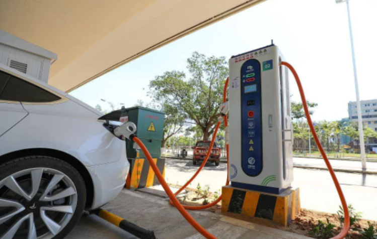
1. My First-Principles View of Electric Vehicle Charging Fire Risk
I begin with a simple reliability perspective. A fire occurs when one or more failure pathways converge with sufficient energy, fuel, and time. In electric vehicle charging, the relevant failure pathways include contact degradation, overload, short circuit, protection failure, insulation aging, power-device degradation, sealing failure, noncompliant installation, poor maintenance, and battery thermal runaway coupled to the charger. I do not assume that these pathways are independent. A loose terminal can increase contact resistance, produce local heating, degrade insulation, and eventually create an arc. A failed seal can admit moisture, reduce insulation resistance, and accelerate tracking. A maintenance gap can allow a damaged charging gun to remain in service, which then creates a poor contact and a high-resistance heat source. The system-level probability of fire can be expressed as a union of contributing events:
$$P_{\mathrm{fire}} = 1-\prod_{i=1}^{n}\left(1-p_i\right)$$
In this expression, \(p_i\) represents the probability of the \(i\)-th contributing failure pathway under the observed operating and environmental conditions. The practical value of the expression is that it forces me to examine multiple pathways rather than to stop at the first burned component. In electric vehicle charging forensics, the first visibly burned component is often a victim of an upstream or downstream fault. I therefore separate the system into energy conversion, energy transmission, energy control, energy storage interface, and human-maintenance layers. Each layer has its own failure signatures, and each signature must be tested against alternative hypotheses.
2. Core Architecture and the Electric Vehicle Charging Energy Path
I classify electric vehicle charging equipment into AC slow charging and DC fast charging because their fire forensics differ substantially. AC slow charging equipment is structurally simpler. It typically includes a distribution switch, control board, metering module, AC harness, charging gun, and communication module. It transfers AC power and performs basic start-stop control, but it does not perform high-power voltage and current conversion inside the charger. Its operating power and heat generation are lower, so its fire probability is generally lower than that of DC fast charging. However, this does not make AC electric vehicle charging inherently safe. Connector wear, cable damage, moisture ingress, poor termination, and upstream protection defects can still create ignition conditions.
DC fast charging equipment is more complex. It includes a high-voltage distribution unit, power conversion modules, a main control unit, a cooling system, charging guns and cables, insulation monitoring, and current protection. The charger rectifies AC input into DC output and delivers it to the vehicle battery. During this process, the main control unit continuously monitors voltage, current, temperature, insulation resistance, and protection status. Because DC fast charging involves higher currents, higher power densities, more power electronics, and greater heat generation, it creates more opportunities for electric vehicle charging fire initiation. I therefore pay particular attention to power modules, DC busbars, contactors, cooling paths, output connectors, and protection coordination in DC fast charging investigations.
| Architecture | Main Components | Energy Conversion | Typical Fire Relevance | Forensic Focus |
|---|---|---|---|---|
| AC slow electric vehicle charging | Distribution switch, control board, metering module, AC harness, charging gun, communication module | No internal high-power AC-to-DC conversion | Lower heat load, but connector, cable, and termination faults remain important | Plug and socket wear, cable crushing, moisture ingress, upstream protection |
| DC fast electric vehicle charging | High-voltage distribution, power modules, main control, cooling, DC output, insulation monitoring, current protection | AC input converted to regulated DC output | Higher current, higher power density, greater heat generation, more protection interactions | Power-device aging, DC busbar contact resistance, cooling failure, output connector arcing, protection coordination |
I use a power-loss balance to explain why DC fast electric vehicle charging deserves close forensic attention. The total loss in a charger can be approximated as:
$$P_{\mathrm{loss}} = \sum I_k^2 R_k + P_{\mathrm{sw}} + P_{\mathrm{mag}} + P_{\mathrm{control}}$$
Here, \(I_k^2 R_k\) represents conduction and contact losses, \(P_{\mathrm{sw}}\) represents switching losses in power electronics, \(P_{\mathrm{mag}}\) represents magnetic losses, and \(P_{\mathrm{control}}\) represents control and auxiliary losses. When current increases, resistive losses rise with the square of current. A small increase in contact resistance at a high-current joint therefore produces a disproportionate temperature rise. This is one reason I treat a slightly discolored DC terminal as a potentially important clue rather than as cosmetic damage.
3. Failure Mode I: Electrical Circuit Faults in Electric Vehicle Charging
Electrical circuit faults are among the most important causes of electric vehicle charging fires. I divide them into contact failure, overload and overheating, short circuit, and protection-device failure. These categories overlap in practice, but separating them helps me organize physical evidence and test alternative hypotheses.
3.1 Contact Failure
Contact failure occurs when a terminal, connector, charging-gun pin, cable joint, busbar joint, relay contact, or contactor contact develops elevated resistance. Causes include virtual connection, oxidation, vibration loosening, spring fatigue, improper crimping, thermal cycling, and contamination. The resulting Joule heating is:
$$Q_J = I^2 R_c t$$
where \(I\) is current, \(R_c\) is contact resistance, and \(t\) is time. The local temperature rise depends on heat generation and heat dissipation:
$$\Delta T \approx \frac{I^2 R_c}{hA}$$
In this approximation, \(h\) is an effective heat-transfer coefficient and \(A\) is the effective heat-dissipation area. The equation is simplified, but it captures the forensic logic: a high-current electric vehicle charging connector with a small contact area and a degraded heat path can reach ignition temperatures even when the nominal current is within the rating of the charger. I look for local melting, pitting, arc craters, metal spatter, carbonized insulation, and heat-affected zones concentrated at current-carrying joints. I also compare the two sides of a connector because asymmetric damage often indicates a poor contact rather than an external flame.
3.2 Overload and Overheating
Overload occurs when electric vehicle charging equipment operates above its rated current or thermal capacity for a sufficient period. In some cases, the protection device rating is too high or the protection curve is mismatched, so the device does not trip before insulation degradation becomes irreversible. I examine whether the charger was operating at a current that the cable, connector, or power module could not sustain. I also examine whether cooling was blocked, fans failed, filters were clogged, or the installation enclosed the charger in a poorly ventilated space. The thermal aging of insulation can be described by an Arrhenius-type relationship:
$$k = A\exp\left(-\frac{E_a}{RT}\right)$$
Here, \(k\) is the degradation rate, \(A\) is a pre-exponential factor, \(E_a\) is activation energy, \(R\) is the gas constant, and \(T\) is absolute temperature. The equation explains why sustained moderate overheating can be as damaging as a short high-temperature event. In electric vehicle charging, thermal aging is cumulative. A charger that has experienced many high-temperature cycles may fail at a lower temperature than a new charger because its insulation and polymer components have already lost mechanical and dielectric strength.
3.3 Short Circuit
I classify short circuits into phase-to-phase, line-to-line, cable-damage, and line-to-ground types. Moisture, dust, salt spray, rodent damage, crushed cables, insulation cracking, and conductive contamination can all reduce dielectric strength. A short circuit produces a high current limited by source impedance:
$$I_{\mathrm{sc}} = \frac{V}{Z_{\mathrm{source}} + Z_{\mathrm{fault}}}$$
The energy released by an arc during a short circuit is:
$$E_{\mathrm{arc}} = \int_{t_1}^{t_2} v(t)i(t)\,dt$$
This arc energy can ignite insulation, cable jackets, dust, and nearby combustible materials. In electric vehicle charging forensics, I distinguish between a short circuit that initiated the fire and a short circuit that resulted from fire damage. That distinction requires laboratory examination of arc beads, melted strands, and globules, together with an assessment of the protection operation sequence.
3.4 Protection-Device Failure
Protection failure includes missing, undersized, oversized, stuck, bypassed, or incorrectly coordinated overcurrent, over-temperature, residual-current, insulation-monitoring, and surge-protection functions. For safe electric vehicle charging, the protection operation time must be shorter than the time required for ignition:
$$t_{\mathrm{trip}} < t_{\mathrm{ignition}}$$
If this inequality is violated, a fault can persist long enough to ignite materials. I check whether the protection device operated, whether it was bypassed, whether its rating matched the cable and connector, and whether the fault current was below the instantaneous trip threshold. I also check whether the charger had valid certification and whether the protection design was appropriate for the installation environment.
| Electrical Fault Type | Physical Mechanism | Typical Location | Forensic Signature | Alternative Hypothesis to Test |
|---|---|---|---|---|
| Contact failure | Elevated contact resistance and Joule heating | Charging gun pins, terminals, busbars, cable joints | Local melting, pitting, arc craters, asymmetric heat damage | External fire heating the connector from outside |
| Overload and overheating | Current above thermal capacity or blocked cooling | Cables, power modules, connectors, enclosure | Generalized insulation hardening, discoloration, thermal deformation | Long-term aging without overload |
| Short circuit | Dielectric breakdown or mechanical damage | Cable runs, DC bus, internal wiring, connectors | Arc beads, fused strands, line-to-ground tracking | Fire-induced short circuit after ignition |
| Protection failure | No trip, delayed trip, wrong rating, bypass | Distribution box, charger input, output protection | Intact fuse, welded contact, bypass wiring, coordination mismatch | Protection operated but fault was downstream |
4. Failure Mode II: Aging and Sealing Failure in Electric Vehicle Charging Equipment
I treat aging as a progressive and often hidden failure mode. Electric vehicle charging equipment is frequently installed outdoors or in semi-open spaces. Temperature cycling, humidity, ultraviolet exposure, salt fog, dust, vibration, and pollution accelerate degradation. Aging is difficult to detect during routine visual inspection because the most important changes occur inside insulation, power devices, seals, and joints.
4.1 Insulation Aging
Insulation aging reduces dielectric strength and increases leakage current. It can lead to tracking, creepage, partial discharge, and eventually short circuit. I model insulation resistance as a time-dependent quantity under environmental stress:
$$R_{\mathrm{ins}}(t) = R_{\mathrm{ins},0}\exp\left(-\lambda t\right)$$
In this simplified model, \(R_{\mathrm{ins},0}\) is the initial insulation resistance and \(\lambda\) is a degradation coefficient influenced by temperature, moisture, contamination, and electrical stress. A low insulation resistance is not merely an electrical measurement issue; in electric vehicle charging it is a fire precursor because leakage current can concentrate at contaminated surfaces and ignite carbonized tracking paths.
4.2 Power-Device Aging
Power modules, contactors, relays, capacitors, gate drivers, and semiconductor devices experience high-frequency voltage and current stress. Aging can increase on-state resistance, switching loss, thermal resistance, and leakage. A degraded device may develop a local hot spot, solder fatigue, bond-wire lift-off, or dielectric breakdown. I examine whether the device failure was the origin or a consequence of cooling loss, overcurrent, or upstream control failure.
4.3 Sealing Failure
Sealing failure admits dust and water into the enclosure. The resulting corrosion, reduced creepage distance, and conductive contamination can produce abnormal conduction and local overheating. I look for water stains, corrosion products, sediment lines, degraded gaskets, damaged cable glands, and condensation patterns. In electric vehicle charging fire investigation, sealing failure is often an enabling condition rather than the ignition event itself. It creates the environment in which another fault becomes dangerous.
| Aging Mode | Stress Factor | Observable Effect | Fire Mechanism | Laboratory Check |
|---|---|---|---|---|
| Insulation aging | Heat, moisture, contamination, electrical stress | Cracking, carbonization, tracking, reduced insulation resistance | Leakage, creepage, short circuit, arc ignition | Insulation resistance, dielectric strength, microscopic tracking analysis |
| Power-device aging | Thermal cycling, high current, switching stress | Increased on-state resistance, hot spots, solder fatigue | Local overheating, device breakdown, arc | Electrical parameter testing, thermal imaging, failure analysis |
| Sealing failure | Rain, dust, salt fog, vibration, gasket aging | Water ingress, corrosion, sediment, condensation | Reduced insulation, conductive path, corrosion heating | Seal inspection, corrosion mapping, contamination analysis |
5. Failure Mode III: Nonstandard Installation and Maintenance in Electric Vehicle Charging
I have found that installation and maintenance defects are often the bridge between a tolerable component weakness and an actual fire. Nonstandard installation includes improvised cable splicing, incorrect grounding, excessive cable bending, undersized conductors, poor crimping, missing strain relief, and inadequate protection coordination. Maintenance defects include delayed repair of damaged charging guns, failure to replace aging cables, lack of thermal monitoring, uncleared combustibles around the charger, and a general culture of construction without sustained maintenance.
Grounding is particularly important in electric vehicle charging. A poor ground connection can prevent fault current from returning safely, causing enclosure potential rise, arcing, and insulation stress. I examine grounding conductors, bonding points, ground resistance, and evidence of arcing at grounding terminals. Cable splicing is another common problem. An improper splice creates a local high-resistance point and a heat source. I compare cable color, strand lay, insulation type, crimp geometry, and marking continuity to detect non-original repairs.
| Installation or Maintenance Defect | Forensic Indicator | Fire Consequence | Investigation Action |
|---|---|---|---|
| Improvised cable splice | Mismatched insulation, non-original connector, local overheating, tape residue | High-resistance joint, local ignition, arc | Photograph, sample splice, compare with original harness |
| Poor grounding | Corroded ground terminal, loose bonding conductor, high ground resistance | Fault current diversion failure, enclosure arcing | Measure ground continuity, inspect bonding points |
| Undersized conductor | Overheated insulation, discolored copper, melted jacket | Overload heating, insulation failure | Verify conductor gauge against charger rating |
| Damaged charging gun left in service | Cracked housing, bent pin, carbonized contact, moisture ingress | Contact resistance, arcing, shock risk | Inspect pin alignment, contact marks, and maintenance records |
| Combustibles stored near charger | Fire spread pattern, ash deposits, melted debris | Rapid fire growth and secondary ignition | Map fuel load and fire spread direction |
6. Failure Mode IV: Battery Thermal Runaway Coupled to Electric Vehicle Charging
I treat battery thermal runaway as a coupled vehicle-charger failure mode. The origin may be in the vehicle battery, but the electric vehicle charging process supplies energy and creates conditions that can accelerate the event. Lithium-ion batteries are sensitive to overcharge, over-temperature, mechanical damage, cell aging, and battery-management-system faults. During charging, abnormal cell behavior can produce heat, gas, and propagation from cell to module to pack.
The thermal balance of a cell can be written as:
$$C_p\frac{dT}{dt} = Q_{\mathrm{gen}} – Q_{\mathrm{loss}}$$
Here, \(C_p\) is the effective heat capacity, \(T\) is temperature, \(Q_{\mathrm{gen}}\) is internal heat generation, and \(Q_{\mathrm{loss}}\) is heat dissipation to the environment. Thermal runaway begins when heat generation exceeds heat dissipation and the cell enters a self-accelerating exothermic chain. At approximately 130 C, the solid electrolyte interphase can decompose and release heat. At approximately 200 C, reactions involving the negative electrode and electrolyte can produce combustible gases such as methane and hydrogen, accompanied by further heat release. Once a cell vents and ignites, the flame can impinge on the charging gun, cable, charger enclosure, and adjacent vehicles.
| Thermal Runaway Stage | Approximate Temperature | Key Process | Forensic Implication |
|---|---|---|---|
| Early self-heating | Below 130 C | Abnormal charge, internal resistance, minor exothermic reaction | BMS data and cell voltage divergence are critical |
| SEI decomposition | About 130 C | Solid electrolyte interphase breakdown and heat release | Cell-level thermal damage may precede visible flame |
| Negative-electrode and electrolyte reaction | About 200 C | Gas generation, strong heat release, venting risk | Combustible gas and pressure damage may explain rapid fire growth |
| Cell venting and ignition | Above onset range | Gas ejection, flame, cell-to-cell propagation | Charging gun and cable damage may be secondary, not origin |
I distinguish battery-origin fire from charger-origin fire by comparing damage severity, smoke patterns, melting direction, and data timelines. If the battery pack shows the most severe internal melting, smoke staining spreads from inside to outside, and the charger shows secondary heat damage, I favor battery thermal runaway as the initiating event. If the charger terminals, busbars, or charging gun root show the most intense local melting and carbonization, and the vehicle damage follows from that point, I favor a charger-origin fault. In electric vehicle charging investigations, this distinction is essential for responsibility allocation and for selecting the correct preventive measure.
7. My Layered Trace Inspection Method
I use a layered trace inspection method based on the principles of overall scene first, local detail second, exterior before interior, and static observation before dynamic reconstruction. I divide the electric vehicle charging fire scene into four zones: the vehicle end, the charging-gun connection end, the charger body end, and the line and distribution end. Each zone has different damage signatures and different evidential value.
| Inspection Zone | Main Targets | Trace Pattern to Record | Interpretive Value |
|---|---|---|---|
| Vehicle end | Battery pack, charge port, underbody, cabin | Melting severity, smoke direction, cell damage, venting residue | Distinguishes battery-origin from charger-origin fire |
| Charging-gun connection end | Gun pins, socket, latch, cable entry | Arc craters, pin discoloration, carbon tracking, asymmetric melting | Identifies contact failure or external heating |
| Charger body end | Power modules, contactors, busbars, control board, enclosure | Local hot spots, component rupture, soot patterns, water ingress | Locates internal electrical or aging failure |
| Line and distribution end | Cables, conduit, protection devices, grounding, terminations | Fused strands, splice marks, protection status, ground corrosion | Tests installation and maintenance hypotheses |
In the overall scene inspection, I record the burned boundary, equipment collapse direction, smoke deposition, char depth, and combustible residue. I then compare the damage gradient across zones. A damage gradient that decreases away from the charger supports a charger-origin hypothesis. A gradient that decreases away from the vehicle battery supports a vehicle-origin hypothesis. I do not rely on a single burn mark. I use the gradient, the smoke pattern, and the electrical evidence together.
In the local refined inspection, I examine terminals, connectors, relay contacts, contactor tips, power-device packages, cable insulation, and enclosure seals. I record whether melting is localized or generalized, whether arc craters face each other, whether copper strands are fused, whether insulation is carbonized along a tracking path, and whether water or dust entered the enclosure. These details allow me to separate contact failure, overload, short circuit, aging, and installation defects.
8. Electrical Evidence Extraction and Laboratory Identification
I follow a strict chain-of-custody procedure for electrical evidence in electric vehicle charging fire investigations. I collect the suspected faulted conductors, terminals, relays, contactors, charging-gun pins, power devices, and protection devices. For each item, I collect a complete section of the trace carrier rather than only the visibly damaged fragment. I use independent numbering, location labels, packaging records, and sealed transport. I ensure that at least two investigators participate in evidence collection when practical, so that the collection process is witnessed and documented.
In the laboratory, I focus on the morphology of metal melt marks, the nature of arc beads, the extent of insulation carbonization, the condition of contacts, and the operating state of protection devices. The key question is whether a melt mark is a primary short-circuit mark, a secondary short-circuit mark caused by fire, or a contact-erosion mark caused by long-term poor contact. I also examine whether the protection device opened normally, welded closed, or never received the fault current.
| Evidence Item | Collection Requirement | Laboratory Test | Forensic Question |
|---|---|---|---|
| Terminals and busbars | Collect complete joint and adjacent conductor | Macroscopic and microscopic melt morphology, metallography | Was there a poor contact, arc, or external heating |
| Cable sections | Include intact insulation on both sides of damage | Strand fusion analysis, insulation carbonization mapping | Was the short circuit primary or secondary |
| Relays and contactors | Preserve contact state and coil circuit | Contact welding, erosion, spring force, coil condition | Did the device fail to open or close properly |
| Protection devices | Photograph and preserve as found | Fuse element examination, trip history, rating verification | Did protection operate within the required time |
| Charging-gun pins | Protect mating surfaces from abrasion | Pin alignment, arc crater mapping, plating damage | Was the connector the origin or a victim |
| Battery-pack samples | Collect cell, busbar, and vent residue samples | Cell melt pattern, gas residue, thermal propagation analysis | Did thermal runaway start in the battery |
I use a likelihood-ratio approach to compare hypotheses when the physical evidence is ambiguous:
$$\Lambda = \frac{P(E \mid H_1)}{P(E \mid H_2)}$$
Here, \(E\) is the observed evidence, \(H_1\) is the hypothesis that the fire originated from a charger fault, and \(H_2\) is the hypothesis that the fire originated from the vehicle battery or an external source. A high likelihood ratio supports \(H_1\), while a low ratio supports \(H_2\). I do not present the ratio as a substitute for engineering judgment. I use it to make the reasoning transparent and to identify which evidence items are most discriminating.
9. Operational Data Traceability for Electric Vehicle Charging Fires
I treat operational data as a form of digital physical evidence. Modern electric vehicle charging stations record charger monitoring data, fault alarms, protection events, output voltage and current, module temperature, insulation resistance, communication status, and battery-management-system data. Video surveillance may also be available. The exact retention period depends on the operator and the applicable specification, but in my investigation I request all available data as early as possible because overwriting is a real risk.
I reconstruct the pre-fire timeline by aligning charger data, battery data, video, and maintenance records. I examine the final hour before ignition for overvoltage, overcurrent, overtemperature, insulation anomalies, protection trips, communication dropouts, and power-module derating. I also examine battery data for cell voltage divergence, temperature rise rate, charge current anomalies, state-of-charge behavior, and thermal-runaway warnings. The temperature rise rate is particularly useful:
$$\dot{T} = \frac{dT}{dt}$$
A sudden increase in \(\dot{T}\) during electric vehicle charging can indicate a developing thermal fault. I compare the measured rate with the normal charging temperature profile and with the charger’s alarm thresholds. If the charger data show a stable output while the battery data show a rapid cell temperature rise, I favor a battery-origin event. If the charger data show contactor chatter, output current instability, or a module overtemperature before the battery anomaly, I favor a charger-origin event.
| Data Source | Key Parameters | Forensic Use | Limitation I Must Consider |
|---|---|---|---|
| Charger monitoring | Input and output voltage, current, power, module temperature, insulation resistance | Detect overload, instability, insulation degradation, protection events | Sensor placement may not capture local hot spots |
| Protection and alarm log | Trip type, time, reset status, fault code | Test protection coordination and fault sequence | Some logs are volatile or overwritten |
| Battery management system | Cell voltage, temperature, current, state of charge, warning history | Detect cell divergence, overcharge, thermal runaway precursors | Data quality depends on sensor coverage |
| Video surveillance | Smoke appearance, flame location, person movement, cable handling | Establish first visible smoke and fire spread direction | Frame rate and viewing angle may be limited |
| Maintenance records | Inspection date, repair type, parts replaced, reported defects | Assess maintenance gaps and prior damage | Records may be incomplete or inconsistent |
| Environmental records | Temperature, humidity, rainfall, wind | Assess moisture ingress, condensation, fire spread | Local microclimate may differ from weather station data |
I also check data integrity. A gap in the log immediately before the fire may indicate power loss, communication failure, or deliberate tampering. I compare the charger clock with the video clock and the battery clock. Time alignment is essential because a few minutes of offset can change the interpretation of cause and effect in electric vehicle charging fire reconstruction.
10. Environmental Inducements and Comprehensive Reasoning
I include environmental factors because they influence both initiation and propagation. Meteorological factors include temperature, humidity, rainfall, solar exposure, and wind. Site factors include combustible storage, dust, oil mist, corrosive gases, and drainage conditions. External factors include physical impact, vehicle contact, rodent damage, and unauthorized modification. Maintenance factors include inspection frequency, defect closure rate, and spare-part quality.
I use a weighted risk score to organize environmental evidence:
$$R = \sum_{j=1}^{m} w_j s_j$$
Here, \(s_j\) is the severity score for the \(j\)-th environmental factor and \(w_j\) is its weight. The score is not a substitute for physical evidence, but it helps me compare sites and identify which environmental conditions deserve deeper investigation. For example, a site with high dust, frequent rain, poor drainage, and no recent inspection has a higher environmental risk score than a clean, sheltered site with regular maintenance. In electric vehicle charging forensics, this score supports the causal chain but does not replace it.
| Environmental Factor | Observed Indicator | Potential Effect on Electric Vehicle Charging Fire | Investigation Action |
|---|---|---|---|
| High humidity and rainfall | Water stains, condensation, corroded terminals | Reduced insulation resistance, tracking, short circuit | Inspect seals, cable glands, and drainage |
| Dust and particulate contamination | Sediment inside enclosure, clogged filters, surface tracking | Creepage, cooling blockage, overheating | Sample contamination and map deposition |
| Corrosive atmosphere | Green or white corrosion products, pitted contacts | Increased contact resistance, ground failure | Analyze corrosion and terminal condition |
| Combustible storage | Ash, melted debris, fire spread beyond charger | Rapid fire growth and secondary ignition | Map fuel load and fire spread pattern |
| Physical impact | Deformed enclosure, cracked gun, bent pin | Insulation damage, contact misalignment, arc | Compare damage with vehicle and site geometry |
| Maintenance gap | Missing inspection records, unrepaired defects | Undetected aging, repeated abnormal operation | Review logs and interview responsible personnel |
11. Integrated Hypothesis Testing and Reporting
I do not conclude an electric vehicle charging fire investigation from a single observation. I build a hypothesis matrix and test each hypothesis against physical evidence, data evidence, environmental evidence, and witness evidence. The hypotheses usually include charger electrical fault, charger aging failure, installation or maintenance defect, battery thermal runaway, external fire, and unknown or undetermined. I evaluate each hypothesis for consistency, discriminating evidence, and unresolved contradictions.
I use a Bayesian-style update to express how evidence changes my belief among hypotheses:
$$P(H_i \mid E) = \frac{P(E \mid H_i)P(H_i)}{\sum_{j=1}^{n}P(E \mid H_j)P(H_j)}$$
In this expression, \(P(H_i)\) is my prior belief in hypothesis \(H_i\), \(P(E \mid H_i)\) is the likelihood of the evidence under that hypothesis, and \(P(H_i \mid E)\) is the posterior belief after considering the evidence. I do not necessarily assign numerical probabilities in every case. The formula reminds me to ask three questions: How likely is this evidence if the hypothesis is true? How likely is it if the hypothesis is false? And how did my belief change after examining the evidence?
| Hypothesis | Supporting Evidence | Contradicting Evidence | Required Confirmation |
|---|---|---|---|
| Charger electrical contact fault | Localized melting at terminal, arc craters, asymmetric pin damage | No current path to the damaged terminal, battery damage more severe | Metallurgical confirmation of primary arc and protection analysis |
| Charger aging failure | Generalized insulation degradation, water ingress, corroded components | Recent replacement, no thermal aging pattern | Insulation and device-level laboratory testing |
| Installation or maintenance defect | Non-original splice, poor grounding, missing inspection records | Compliant installation confirmed by as-built records | Ground resistance measurement and splice analysis |
| Battery thermal runaway | Cell voltage divergence, rapid temperature rise, internal pack melting | Charger terminal melting precedes battery data anomaly | Battery forensic analysis and data timeline alignment |
| External fire | Fire spread from outside, unrelated fuel load, no internal electrical fault | Arc marks inside charger, protection operation | Scene reconstruction and ignition source exclusion |
My report separates observations from interpretations. Observations include burn patterns, component conditions, data logs, and laboratory results. Interpretations include the probable origin, the failure sequence, the contributing factors, and the confidence level. I state what I can support with evidence, what I cannot determine, and what additional testing would resolve the remaining uncertainty. This discipline is particularly important in electric vehicle charging fire cases because the public, operators, manufacturers, insurers, and regulators may all rely on the report for different decisions.
12. Prevention and Pre-Forensic Governance
I prefer to prevent electric vehicle charging fires rather than only investigate them. Prevention begins with design review, certification, protection coordination, connector quality, sealing, thermal management, and installation inspection. It continues with condition monitoring, periodic maintenance, thermal imaging, insulation testing, connector inspection, and data analytics. I recommend that operators treat electric vehicle charging assets as safety-critical equipment rather than as passive outlets.
| Control Layer | Recommended Measure | Effect on Electric Vehicle Charging Fire Risk | Verification Method |
|---|---|---|---|
| Design | Coordinate protection with cable and connector ratings; use certified components | Prevents sustained faults and undersized protection | Design review, type test records, protection coordination study |
| Installation | Verify grounding, torque, cable bending radius, sealing, and strain relief | Reduces contact resistance and moisture ingress | Commissioning inspection, torque records, ground resistance test |
| Monitoring | Track temperature, current, voltage, insulation resistance, and fault logs | Detects degradation before ignition | Alarm review, trend analysis, sensor calibration |
| Maintenance | Inspect guns, cables, terminals, fans, filters, and seals on a fixed schedule | Removes damaged components and blocked cooling paths | Checklists, photographs, repair records |
| Housekeeping | Keep combustibles away from chargers and cable storage areas | Limits fire growth and secondary ignition | Site inspection and housekeeping audit |
| Data governance | Retain charger, protection, battery, and video data for the required period | Preserves evidence for traceability and investigation | Data integrity audit and retention test |
13. My Concluding Protocol for Electric Vehicle Charging Fire Investigation
My protocol begins with safety and scene control, then moves to overall documentation, layered trace inspection, electrical evidence collection, data preservation, environmental assessment, laboratory identification, and hypothesis testing. I keep the electric vehicle charging energy path at the center of the analysis. I compare the vehicle end, the charging-gun connection, the charger body, and the line and distribution end. I test contact failure, overload, short circuit, protection failure, aging, sealing failure, installation defect, maintenance gap, and battery thermal runaway as competing and interacting hypotheses. I use formulas to make heat generation, insulation degradation, protection timing, arc energy, thermal runaway, and evidence weighting explicit, but I do not let formulas replace physical observation.
The most defensible conclusion in an electric vehicle charging fire investigation is one that explains the entire evidence set: the burn pattern, the electrical damage, the protection state, the data timeline, the environmental conditions, and the maintenance history. I do not treat a burned terminal as automatic proof of a terminal fault, and I do not treat a burned battery as automatic proof of battery failure. I reconstruct the sequence. I identify the first event that can be supported by evidence. I separate primary faults from secondary fire effects. I state confidence and uncertainty. In my experience, this disciplined approach improves origin determination, supports responsibility allocation, and provides practical feedback for electric vehicle charging design, installation, maintenance, monitoring, and emergency planning.