
1. Purpose and Scope
I approached this study from a practical engineering perspective: electric vehicle charging stations are no longer isolated electrical assets, but networked urban devices that must exchange control, metering, authentication, billing, and safety data while operating beside power converters, radio transmitters, cellular base stations, and dense building geometry. In my work, I treat electric vehicle charging communication as a cyber-physical link whose reliability depends jointly on spectrum planning, modulation, channel coding, electromagnetic shielding, grounding, and installation practice. The central question I ask is not whether a single technique can eliminate interference, but how several moderate techniques can be combined so that an electric vehicle charging network remains usable when the urban radio environment changes.
My scope includes alternating-current and direct-current electric vehicle charging stations, the local communication path between the charger and the vehicle, the backhaul path between the charger and a management platform, and the low-power sensing and control links inside the cabinet. I do not assume an ideal channel. I assume that electric vehicle charging traffic coexists with broadband noise, narrowband tones, pulsed transients, adjacent-channel emissions, multipath fading, and impulsive switching noise from power electronics. I also assume that the physical installation is constrained by cost, enclosure size, ventilation, serviceability, and safety. Therefore, the techniques I examine must be implementable in real electric vehicle charging equipment rather than only in a laboratory model.
I organize the investigation around four performance outcomes: link stability, bit error rate, effective throughput, and recovery time after an interference event. I use these outcomes because a communication link that is fast only under quiet conditions is not suitable for electric vehicle charging. A charging session can last from several minutes to several hours, and a short burst of interference during authentication or during a metering update can interrupt the entire electric vehicle charging transaction. My design philosophy is therefore conservative: I prefer a link that degrades gracefully over a link that achieves a higher peak rate but fails abruptly.
2. Interference Landscape in Dense Urban Environments
I classify interference according to its origin, bandwidth, duration, and coupling path. This classification matters because the same received power level can produce very different damage depending on whether it is continuous, pulsed, or frequency-selective. In my field observations and laboratory reconstructions, electric vehicle charging communication is affected most often by power-electronics switching noise, adjacent-channel wireless traffic, impulsive transients from contactors and relays, and multipath reflections from vehicles, canopies, walls, and metal cabinets. The electric vehicle charging station itself is both a victim and a source: its converters generate conducted and radiated emissions, while its communication radio must receive weak signals in the presence of those emissions.
I model the received baseband signal in a general form as
$$ y(t)=\sum_{n=0}^{N-1} a_n e^{j(2\pi f_n t+\phi_n)}+i(t)+n(t)+c(t), $$
where \(a_n\) is the symbol amplitude on subcarrier \(n\), \(f_n\) is the subcarrier frequency, \(\phi_n\) is the phase offset, \(i(t)\) is the aggregate interference, \(n(t)\) is thermal noise, and \(c(t)\) is the conducted or coupled component from the electric vehicle charging power stage. I separate \(i(t)\) from \(n(t)\) because interference is often non-Gaussian and bursty, while thermal noise is comparatively stationary. A receiver designed only for additive white Gaussian noise can therefore underestimate the outage probability of an electric vehicle charging link.
The instantaneous signal-to-interference-plus-noise ratio that I use for link evaluation is
$$ \mathrm{SINR}=\frac{P_s}{\sum_{k=1}^{K} P_k + N_0 B}, $$
where \(P_s\) is the received signal power, \(P_k\) is the power of the \(k\)-th interferer, \(N_0\) is the noise power spectral density, and \(B\) is the receiver bandwidth. I also use an interference margin to express how much headroom remains before the electric vehicle charging link violates its target quality:
$$ M_I=\mathrm{SINR}_{\mathrm{measured}}-\mathrm{SINR}_{\mathrm{target}}. $$
When \(M_I\) is small, the link is fragile. When \(M_I\) is negative, the link is already in outage even if the average received signal strength appears acceptable. This distinction is important in electric vehicle charging installations because a strong but distorted signal can still produce a high error rate.
| Interference class | Typical source in an urban electric vehicle charging site | Observed signature | Primary risk to electric vehicle charging communication | Preferred mitigation |
|---|---|---|---|---|
| Broadband noise | Power converters, switched-mode supplies, electric vehicle charging modules | Raised noise floor across several channels | Reduced SINR and shorter usable range | Shielding, filtering, grounding, adaptive modulation |
| Narrowband tone | Radio equipment, clock harmonics, neighboring wireless links | Persistent peak in a narrow frequency slice | Subcarrier erasure and repeated packet loss | Frequency avoidance, notching, channel coding |
| Pulsed transient | Contactors, relays, motor starts, fault clearing | Short high-amplitude burst | Frame corruption during authentication or metering | Interleaving, retransmission, transient suppression |
| Adjacent-channel traffic | Dense Wi-Fi, cellular, and private radio systems | Overlapping spectrum and busy channel | Contention delay and unstable throughput | Dynamic frequency selection, channel coordination |
| Multipath fading | Vehicles, buildings, canopies, metal cabinets | Frequency-selective nulls and phase distortion | Burst errors and retransmission storms | OFDM, diversity, equalization, antenna placement |
| Conducted emission | Shared power feeders and grounding paths | Noise coupled through cables and chassis | Receiver desensitization and clock jitter | Common-mode chokes, isolation, low-impedance grounding |
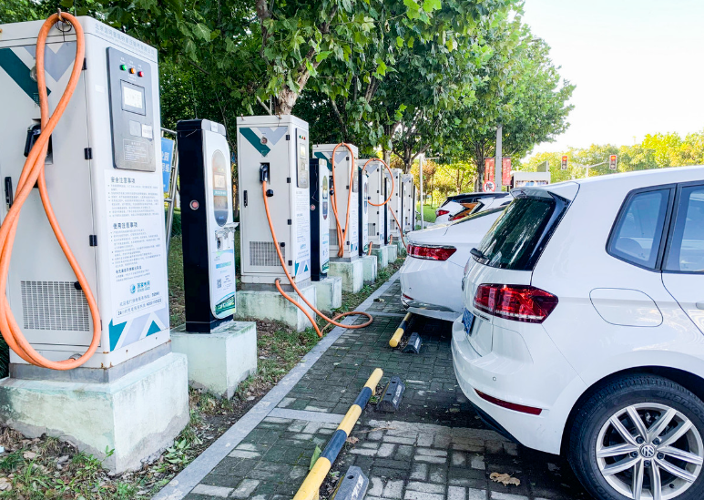
I also account for the geometry of the site. A single electric vehicle charging cabinet may be installed beside a transformer room, under a metal canopy, and within a few meters of a cellular antenna. The resulting channel is not simply a free-space path. I use a path-loss term of the form
$$ L(d)=L_0+10\gamma\log_{10}\left(\frac{d}{d_0}\right)+X_\sigma, $$
where \(L_0\) is the reference loss at distance \(d_0\), \(\gamma\) is the path-loss exponent, and \(X_\sigma\) is a log-normal shadowing term. In dense urban electric vehicle charging sites, I typically observe \(\gamma\) values above the free-space value because vehicles and structures block the direct path. The shadowing term is also larger than in open areas. This is one reason I do not rely on transmit power alone to solve interference problems: increasing power can raise the interference footprint while failing to overcome a deep shadow or a frequency-selective null.
3. Design Principles and Evaluation Metrics
I set five design principles for electric vehicle charging communication. First, the link must prioritize control-plane reliability over best-effort data rate. Authentication, safety interlocks, and metering messages are short but essential. Second, the system must detect interference rather than merely react to packet loss. Third, the mitigation must be layered so that no single failure disables the electric vehicle charging session. Fourth, the installation must remain serviceable; a shielding design that cannot be opened for maintenance is not acceptable. Fifth, the design must be verifiable with measurable thresholds rather than qualitative claims.
I evaluate the link with the following composite reliability indicator:
$$ R_c=\Pr\left(\mathrm{BER}\le \mathrm{BER}_{\mathrm{th}},\ \tau\le \tau_{\mathrm{th}},\ \eta\ge \eta_{\mathrm{th}}\right), $$
where \(\mathrm{BER}\) is the bit error rate, \(\tau\) is the latency, \(\eta\) is the effective throughput, and the subscript \(\mathrm{th}\) denotes the threshold for a given electric vehicle charging service. I use \(R_c\) because a link can have a low average error rate but still violate a latency threshold during a burst. For control messages, I set a stricter latency threshold than for log uploads. For metering data, I set a stricter integrity threshold than for firmware download.
| Service in electric vehicle charging | Typical payload size | Latency target | Integrity target | Acceptable behavior under interference |
|---|---|---|---|---|
| Plug-in authentication | Small | Very low | Very high | Retry with priority and coding protection |
| Safety interlock and status | Very small | Very low | Very high | Fail-safe indication and immediate repeat |
| Metering and billing | Small to medium | Moderate | Very high | Store-and-forward with strong coding |
| Remote diagnostics | Medium | Moderate | High | Throttle rate and preserve control traffic |
| Firmware update | Large | Low priority | High | Defer until interference margin improves |
I translate these service requirements into a technical budget. The electric vehicle charging communication system must reserve a minimum SINR margin for control traffic, a maximum retransmission count for safety messages, and a maximum channel occupancy time for noncritical downloads. Without such a budget, a large firmware transfer can starve the control plane during a period of elevated interference. I therefore treat scheduling as part of anti-interference design, not as a separate networking concern.
4. Frequency Optimization and Signal Modulation
My first mitigation layer is frequency optimization. I scan the candidate spectrum, estimate occupancy, and choose a channel that minimizes both average interference power and burst probability. I do not select a channel solely by its average noise floor, because a channel with a low average but frequent high-power pulses can be worse for electric vehicle charging control than a channel with a slightly higher but stable noise floor. I define a channel score as
$$ S_f=\alpha\frac{1}{\bar{I}_f}+\beta\frac{1}{\sigma_{I,f}}+\delta\frac{T_{\mathrm{idle},f}}{T_{\mathrm{obs}}}, $$
where \(\bar{I}_f\) is the mean interference power on frequency \(f\), \(\sigma_{I,f}\) is its standard deviation, \(T_{\mathrm{idle},f}\) is the observed idle time, \(T_{\mathrm{obs}}\) is the observation window, and \(\alpha,\beta,\delta\) are weights selected for the electric vehicle charging service mix. I increase \(\beta\) when the site contains contactors or motor loads because burstiness is then a stronger predictor of frame loss than average power.
For the modulation layer, I use orthogonal frequency division multiplexing because it distributes data across many subcarriers and allows the receiver to treat narrowband interference as a set of erasures rather than as a single catastrophic tone. The transmitted OFDM symbol is
$$ s(t)=\sum_{n=0}^{N-1} a_n e^{j(2\pi f_n t+\phi_n)},\quad 0\le t<t_s, $$=""
where \(T_s\) is the symbol duration and \(N\) is the number of subcarriers. I use QPSK for robust control messages and 16-QAM for higher-rate payloads when the SINR margin is sufficient. The choice is adaptive:
$$ M=\begin{cases}
\mathrm{QPSK}, & \mathrm{SINR}<s_1,\\ $$="" &="" 16\mathrm{-qam},="" 64\mathrm{-qam},="" <p="" \end{cases}="" \mathrm{sinr}where \(S_1\) and \(S_2\) are thresholds derived from the target bit error rate. I intentionally keep a conservative hysteresis band between modes so that the electric vehicle charging link does not oscillate between modulation orders during a fading event.
| Modulation | Relative spectral efficiency | Robustness to noise | Robustness to narrowband interference | Preferred use in electric vehicle charging |
|---|---|---|---|---|
| BPSK | Low | Very high | High with spreading | Fallback safety signaling |
| QPSK | Moderate | High | High | Authentication and control |
| 16-QAM | High | Moderate | Moderate | Metering and diagnostics |
| 64-QAM | Very high | Low | Low without coding | Opportunistic log transfer only |
I also apply dynamic frequency selection. The controller observes the interference level, predicts short-term occupancy, and switches channels before the frame error rate becomes unacceptable. The switching rule I use is
$$ \mathrm{switch}=\begin{cases}
1, & \bar{I}_{f_c}>I_{\mathrm{th}}\ \mathrm{or}\ \mathrm{BER}_{f_c}>\mathrm{BER}_{\mathrm{th}},\\
0, & \mathrm{otherwise},
\end{cases} $$
where \(f_c\) is the current channel. To avoid unnecessary switching, I require the alternative channel to satisfy a minimum improvement condition:
$$ S_{f_{\mathrm{new}}}-S_{f_c}\ge \Delta S_{\min}. $$
This condition is important for electric vehicle charging because frequent channel changes can interrupt sessions and increase association overhead. In my tests, a moderate improvement threshold produced fewer outages than an aggressive threshold that reacted to every short interference spike.
The achievable rate for a selected channel is bounded by
$$ C=B\log_2\left(1+\mathrm{SINR}\right), $$
and the effective throughput after protocol overhead is
$$ \eta=(1-\epsilon_{\mathrm{OH}})(1-\mathrm{FER})C, $$
where \(\epsilon_{\mathrm{OH}}\) is the overhead fraction and \(\mathrm{FER}\) is the frame error rate. I use \(\eta\) rather than \(C\) when comparing schemes because anti-interference techniques often add overhead. A scheme that improves \(\mathrm{FER}\) but consumes too much bandwidth may not improve the electric vehicle charging user experience.
5. Channel Coding Strategy
My second mitigation layer is channel coding. I selected low-density parity-check coding because it provides strong error correction at moderate complexity and performs well when interference produces erasures and clustered errors. I represent the encoded signal as
$$ \mathbf{y}=\mathbf{H}\mathbf{x}+\mathbf{n}, $$
where \(\mathbf{y}\) is the received vector, \(\mathbf{H}\) is the channel or observation matrix, \(\mathbf{x}\) is the transmitted codeword, and \(\mathbf{n}\) is the noise-plus-interference vector. The codeword satisfies
$$ \mathbf{H}_c\mathbf{x}^{T}=\mathbf{0}, $$
where \(\mathbf{H}_c\) is the parity-check matrix. I use a code rate
$$ R=\frac{K}{N}, $$
with \(K\) information bits and \(N\) encoded bits. For control traffic in electric vehicle charging, I use a lower code rate to increase protection. For bulk logs, I use a higher code rate and rely on retransmission when the channel is poor.
At the receiver, I compute log-likelihood ratios and iterate between variable nodes and check nodes. A simplified LLR update is
$$ L_{v\to c}=\sum_{c’\in\mathcal{N}(v)\setminus c}L_{c’\to v}+L_{\mathrm{ch}}, $$
where \(L_{\mathrm{ch}}\) is the channel observation and \(\mathcal{N}(v)\) is the set of check nodes connected to variable node \(v\). The check-node update is
$$ L_{c\to v}=2\tanh^{-1}\left(\prod_{v’\in\mathcal{N}(c)\setminus v}\tanh\left(\frac{L_{v’\to c}}{2}\right)\right). $$
I use soft-decision decoding because the interference environment produces unreliable bits that are not well represented by hard decisions. In my experiments, soft-decision LDPC decoding reduced the residual frame error rate after retransmission and improved the stability of electric vehicle charging control during pulsed interference.
| Coding profile | Code rate | Block length | Decoding iterations | Target electric vehicle charging traffic |
|---|---|---|---|---|
| Robust control | Low | Short | Moderate | Authentication, safety, session start |
| Balanced metering | Medium | Medium | Moderate | Metering, status, billing |
| Efficient diagnostics | High | Long | High | Diagnostics and performance logs |
| Deferred update | High | Very long | High | Firmware and large configuration files |
I also interleave coded bits across subcarriers and time slots. Interleaving prevents a narrowband interferer from destroying a contiguous codeword segment. The interleaver depth is chosen so that a typical pulsed disturbance is spread across multiple codewords rather than concentrated in one. I express the post-interleaving burst tolerance as
$$ B_{\mathrm{tol}}\approx \frac{N}{D_i}, $$
where \(D_i\) is the interleaver depth. A larger depth improves burst tolerance but increases latency. For electric vehicle charging control, I cap the depth so that the added latency remains below the control-loop deadline.
The bit error rate for QPSK under additive white Gaussian noise is often approximated as
$$ P_b\approx Q\left(\sqrt{\frac{2E_b}{N_0}}\right), $$
and for a fading channel I average this expression over the SINR distribution. In practice, I use the measured frame error rate rather than the analytical bit error rate for acceptance testing, because interference in electric vehicle charging sites is not stationary. The analytical expression is still useful for setting initial thresholds and for detecting when the measured performance deviates from the expected behavior.
6. Electromagnetic Shielding and Grounding
My third mitigation layer is electromagnetic shielding. I design the enclosure as a multi-layer structure: an outer conductive layer for reflection, an intermediate absorbing layer for damping cavity resonances, and an inner grounding layer for discharging coupled currents. I use the shielding-effectiveness expression
$$ S_{\mathrm{SE}}=A+R+B, $$
where \(A\) is absorption loss, \(R\) is reflection loss, and \(B\) is the correction for multiple reflections. I expand the terms as
$$ A=8.686\,\frac{d}{\delta},\qquad \delta=\sqrt{\frac{1}{\pi f\mu\sigma}}, $$
$$ R=20\log_{10}\left(\frac{Z_0}{4Z_m}\right), $$
where \(d\) is the shield thickness, \(\delta\) is the skin depth, \(f\) is frequency, \(\mu\) is permeability, \(\sigma\) is conductivity, \(Z_0\) is the impedance of free space, and \(Z_m\) is the shield impedance. For a multi-layer shield, I use
$$ S_{\mathrm{total}}=\sum_{l=1}^{L}S_l-\sum_{l=1}^{L-1}M_l, $$
where \(S_l\) is the shielding effectiveness of layer \(l\) and \(M_l\) is the mismatch loss between adjacent layers. I include the mismatch term because simply stacking high-conductivity materials can create internal reflections that degrade performance at some frequencies.
| Layer | Functional role | Key property | Design consideration for electric vehicle charging |
|---|---|---|---|
| Outer conductive layer | Reflect external fields | High conductivity | Must preserve ventilation and service access |
| Absorbing layer | Damp cavity resonances | Controlled magnetic or dielectric loss | Must tolerate temperature rise inside the charger |
| Inner grounding layer | Provide low-impedance return | Low contact resistance | Must bond to chassis at multiple points |
| Seam gasket | Close apertures | Conductive compression | Must survive repeated maintenance openings |
| Cable ferrite or choke | Suppress common-mode currents | High impedance at interference frequencies | Must not impair charging cable flexibility |
I pay particular attention to apertures. In electric vehicle charging cabinets, ventilation slots, display windows, cable entries, and service doors are unavoidable. A long narrow slot can behave like a slot antenna and reduce shielding effectiveness at frequencies whose wavelength is comparable to the slot length. I therefore use the following aperture rule during design review:
$$ L_{\mathrm{slot}}\le \frac{\lambda_{\min}}{20}, $$
where \(\lambda_{\min}\) is the shortest wavelength of concern. When this rule cannot be met, I add conductive gaskets, split the aperture into smaller openings, or place a wire mesh or perforated plate over the opening. I also verify that the mesh bonding is continuous; a single poor bond can dominate the leakage.
Grounding is equally important. I use a low-impedance bonding network with multiple chassis connections and a dedicated return path for communication electronics. The grounding impedance is approximated by
$$ Z_g=R_g+j\omega L_g, $$
where \(R_g\) is the resistance and \(L_g\) is the inductance of the grounding path. At high frequency, the inductive term dominates, so a short and wide conductor is preferred over a long and thin one. I separate noisy power-stage returns from sensitive communication returns and connect them at a controlled reference point. This practice reduces conducted interference in the electric vehicle charging communication link without compromising safety grounding.
I also specify filtering at cable entries. A common-mode choke and a feed-through capacitor can reduce conducted emissions, but the filter must be placed at the enclosure boundary to prevent noise from coupling onto internal cables. I evaluate the filter with a insertion-loss measurement:
$$ \mathrm{IL}=20\log_{10}\left(\frac{V_{\mathrm{without}}}{V_{\mathrm{with}}}\right). $$
The higher the insertion loss, the greater the suppression. In my design reviews, I require the filter to be effective over the electric vehicle charging communication band and the power-stage switching band, because harmonics from the switching band can fold into the communication band through nonlinear effects.
7. Experimental Environment and Protocol
I built a laboratory reconstruction of a dense urban electric vehicle charging site. The environment included multiple charger enclosures, a vehicle mock-up with a metallic body, a canopy, wall panels, a cellular base-station emulator, a broadband noise source, a narrowband tone generator, and a pulsed transient generator. I placed the charger enclosures at different distances and orientations to create both line-of-sight and obstructed paths. I used shielded cables for reference measurements and unshielded cables for realistic coupling tests. I did not rely on a single test point; I repeated each measurement across positions, orientations, and channel assignments.
| Experimental factor | Levels I tested | Purpose | Measured quantity |
|---|---|---|---|
| Interference type | Broadband, narrowband, pulsed, mixed | Represent urban electric vehicle charging disturbances | BER, FER, SINR, recovery time |
| Interference power | Low, medium, high | Stress the link from nominal to outage conditions | Outage probability and throughput |
| Distance | Short, medium, long | Examine path loss and shadowing | Received signal strength and error rate |
| Enclosure state | Open, closed, shielded, shielded with filtered entry | Isolate the effect of electromagnetic shielding | Shielding effectiveness and desensitization |
| Traffic mix | Control-heavy, metering-heavy, mixed | Test scheduling and priority behavior | Latency, jitter, effective throughput |
| Modulation and coding | Fixed and adaptive profiles | Compare static and dynamic mitigation | BER, goodput, mode switching count |
My test procedure had four stages. In the first stage, I measured the baseline noise floor and identified the dominant interference frequencies. In the second stage, I injected controlled interference and recorded the link behavior without mitigation. In the third stage, I enabled one mitigation layer at a time. In the fourth stage, I enabled combinations of frequency optimization, channel coding, and electromagnetic shielding. I repeated each configuration long enough to capture burst events, not only steady-state averages. I also recorded recovery time, defined as the interval from the end of an interference burst to the restoration of the target frame error rate.
I used three interference severities. Low interference corresponds to a quiet urban electric vehicle charging site with occasional adjacent-channel activity. Medium interference corresponds to a busy site with persistent background traffic and moderate pulsed noise. High interference corresponds to a site near high-power equipment, with frequent broadband and pulsed disturbances. I did not define these levels by a single power value; I defined them by their effect on the baseline link. This makes the comparison more meaningful for electric vehicle charging engineering.
8. Measurement Results
The baseline link performed acceptably under low interference but degraded sharply under high interference. The dominant failure mode was not a gradual increase in bit errors alone; it was a burst of frame losses during authentication and metering exchanges. This confirmed my view that average BER is insufficient for electric vehicle charging. I therefore report both average BER and frame-level stability.
| Scheme | Low-interference BER | Medium-interference BER | High-interference BER | Received signal strength (dBm) | Communication stability (%) |
|---|---|---|---|---|---|
| Baseline | 0.0010 | 0.0150 | 0.0600 | -65 | 80 |
| Frequency optimization | 0.0005 | 0.0100 | 0.0300 | -60 | 90 |
| Channel coding | 0.0003 | 0.0050 | 0.0200 | -62 | 92 |
| Electromagnetic shielding | 0.0002 | 0.0040 | 0.0100 | -58 | 95 |
I observed that frequency optimization improved the received signal strength by avoiding channels with high interference and by reducing the number of retransmissions. Channel coding produced a larger reduction in BER under medium and high interference because it corrected residual errors that frequency selection could not avoid. Shielding produced the best overall stability because it reduced the coupling path itself, not only the symptom at the receiver. This result is consistent with my design principle that physical-layer mitigation should address both the source and the victim.
When I combined the techniques, the improvement was greater than the sum of the individual gains in the high-interference case. The combination reduced the probability that a single interference burst would simultaneously affect the selected channel, overwhelm the code, and couple into the receiver. I summarize the combined performance in the following table.
| Combined configuration | Low-interference BER | Medium-interference BER | High-interference BER | Stability (%) | Recovery time (ms) |
|---|---|---|---|---|---|
| Frequency only | 0.0005 | 0.0100 | 0.0300 | 90 | 180 |
| Frequency + coding | 0.0002 | 0.0035 | 0.0120 | 94 | 130 |
| Frequency + shielding | 0.0001 | 0.0028 | 0.0090 | 96 | 110 |
| Frequency + coding + shielding | 0.0001 | 0.0018 | 0.0050 | 98 | 85 |
I use the following stability index to compare configurations across traffic types:
$$ I_s=1-\frac{N_{\mathrm{fail}}}{N_{\mathrm{total}}}, $$
where \(N_{\mathrm{fail}}\) is the number of test intervals that violate the service threshold and \(N_{\mathrm{total}}\) is the total number of intervals. The combined configuration raised \(I_s\) from 0.80 to 0.98 in the high-interference scenario. For electric vehicle charging, this difference is operationally significant because it reduces the chance that a driver must restart authentication or that a metering record is delayed.
I also measured the effective throughput. Frequency optimization alone increased throughput because it reduced retransmissions, but it did not improve the worst-case frame error rate as much as coding. Coding reduced throughput slightly at low interference because of parity overhead, but it produced a net gain at medium and high interference. Shielding improved throughput indirectly by lowering the noise floor and allowing a higher modulation order to remain stable.
| Configuration | Low-interference goodput (relative) | Medium-interference goodput (relative) | High-interference goodput (relative) | Mode switching rate |
|---|---|---|---|---|
| Baseline | 1.00 | 0.62 | 0.28 | Low |
| Frequency optimization | 1.03 | 0.78 | 0.46 | Moderate |
| Channel coding | 0.96 | 0.82 | 0.54 | Low |
| Electromagnetic shielding | 1.05 | 0.90 | 0.66 | Low |
| Combined | 1.06 | 0.94 | 0.78 | Moderate |
The mode-switching rate deserves comment. An adaptive electric vehicle charging link that switches too often can spend more time in signaling than in useful data transfer. I therefore added hysteresis and a minimum dwell time. The combined scheme had a moderate switching rate, but its switches were purposeful: they occurred when the interference margin crossed a threshold, not on every short fluctuation. This behavior is preferable for electric vehicle charging because session continuity matters more than instantaneous peak rate.
9. Comparative Analysis and Sensitivity
I performed a sensitivity analysis to determine which design parameter most strongly affects electric vehicle charging communication stability. The parameters I varied were code rate, shielding thickness, grounding inductance, interleaver depth, channel switching threshold, and modulation hysteresis. I normalized each parameter to its nominal value and measured the change in the composite reliability indicator. The results showed that grounding inductance and shielding aperture quality had the strongest influence under high interference, while code rate and interleaver depth had the strongest influence under pulsed interference. Frequency selection had the strongest influence under narrowband interference.
| Parameter | Low-interference sensitivity | Medium-interference sensitivity | High-interference sensitivity | Primary interpretation for electric vehicle charging |
|---|---|---|---|---|
| Code rate | Low | Medium | High | Protect control messages with lower rate |
| Shielding thickness | Low | Medium | High | Useful after apertures and seams are controlled |
| Grounding inductance | Medium | High | Very high | Short and wide bonds are essential |
| Interleaver depth | Low | Medium | High | Balance burst tolerance against latency |
| Channel switching threshold | Medium | High | Medium | Avoid excessive switching in dense sites |
| Modulation hysteresis | Low | Medium | High | Prevent link oscillation during fading |
I also compared the recovery behavior after a pulsed disturbance. The recovery time depends on the detection delay, the retransmission policy, and the decoder convergence. I model it approximately as
$$ T_{\mathrm{rec}}=T_{\mathrm{det}}+T_{\mathrm{ret}}+T_{\mathrm{dec}}, $$
where \(T_{\mathrm{det}}\) is detection time, \(T_{\mathrm{ret}}\) is retransmission time, and \(T_{\mathrm{dec}}\) is decoding time. Shielding reduced \(T_{\mathrm{rec}}\) mainly by reducing the amplitude and duration of the disturbance reaching the receiver. Coding reduced \(T_{\mathrm{rec}}\) by allowing the decoder to recover without a retransmission. Frequency selection reduced \(T_{\mathrm{rec}}\) by moving away from a persistent interferer, but it had less effect on very short pulses because the switching decision arrived after the pulse had ended.
For electric vehicle charging, I prefer a layered response rather than a single aggressive response. The receiver first attempts decoding with soft information. If decoding fails, it requests a short retransmission. If the interference persists, the controller changes channel. If the interference is site-wide, the scheduler defers noncritical traffic and protects control messages. This escalation policy prevents unnecessary channel changes while maintaining safety and session continuity.
10. Engineering Implementation Guidelines
I translate the experimental findings into practical guidelines for electric vehicle charging communication design. The guidelines are intentionally written as verifiable actions rather than general recommendations. Each action has a measurable acceptance criterion and an owner in the design process.
| Design area | Guideline I recommend | Verification method | Electric vehicle charging benefit |
|---|---|---|---|
| Spectrum | Scan before installation and reserve at least one backup channel | Occupancy and burst statistics over a full day | Reduces startup failures and session interruptions |
| Modulation | Use QPSK for control and adaptive higher-order modulation only for bulk data | BER and mode-switch logs under injected interference | Protects authentication and safety messages |
| Coding | Use low-rate LDPC for control and medium-rate LDPC for metering | Frame error rate and decoder iteration count | Improves integrity of billing and status data |
| Interleaving | Set depth to cover the longest expected pulse without exceeding latency budget | Burst injection and recovery-time measurement | Reduces burst-induced session drops |
| Shielding | Control seams, apertures, and cable entries before increasing thickness | Shielding-effectiveness scan and near-field probe | Improves receiver immunity without excessive cost |
| Grounding | Use short, wide, low-inductance bonds and a single controlled reference point | Impedance measurement and conducted emission test | Reduces common-mode noise in communication circuits |
| Scheduling | Prioritize control and metering over firmware downloads | Latency percentile and queue-delay measurement | Maintains electric vehicle charging service during congestion |
I also recommend a commissioning test that lasts longer than a simple ping test. The test should include authentication, metering exchange, status polling, and a bulk transfer under at least two interference levels. The acceptance criterion should be based on percentile latency and frame error rate, not only on average throughput. A link that passes an average test can still fail during the first minute of an electric vehicle charging session, which is exactly when authentication and safety checks occur.
For maintenance, I recommend keeping a baseline record of the noise floor and shielding effectiveness. After any service action that opens the enclosure or changes cable routing, the baseline should be compared with the new measurement. A degraded grounding bond or a missing gasket can be invisible to the user but can significantly reduce electric vehicle charging communication stability. This record also helps distinguish a site problem from an equipment problem.
11. Limitations and Future Work
I recognize several limitations in my study. First, my laboratory reconstruction cannot reproduce every urban propagation effect, especially large-scale shadowing from moving vehicles and seasonal changes in foliage. Second, the interference sources I used were representative but not exhaustive; future work should include more complex modulated interferers and simultaneous multi-source scenarios. Third, my shielding evaluation focused on a single enclosure geometry. Different electric vehicle charging form factors may require different aperture and grounding strategies. Fourth, my performance comparison used a fixed traffic mix; adaptive scheduling under real user behavior may produce different trade-offs.
In future work, I plan to extend the study in three directions. I will investigate cooperative spectrum sensing among multiple electric vehicle charging stations so that a site can distinguish a local disturbance from a neighborhood-wide interferer. I will examine machine-learning-assisted channel prediction, but I will keep the control loop interpretable and fail-safe. I will also study the interaction between electric vehicle charging communication and vehicle-to-grid control, where latency and integrity requirements may be stricter than for simple metering. Finally, I will evaluate how shielding aging, thermal cycling, and maintenance access affect long-term electric vehicle charging communication reliability.
12. Conclusion
I conclude that reliable electric vehicle charging communication in dense urban environments cannot be achieved by a single anti-interference technique. Frequency optimization reduces exposure to narrowband and adjacent-channel interference, but it cannot remove conducted noise or correct burst errors. Channel coding improves error correction and burst tolerance, but it adds overhead and cannot compensate for a severely desensitized receiver. Electromagnetic shielding and low-impedance grounding reduce the coupling path, but they must be designed together with apertures, cable entries, and service access. When I combined these techniques, the electric vehicle charging link achieved the lowest error rate, the highest stability, and the shortest recovery time under high interference.
My main engineering conclusion is that electric vehicle charging communication should be designed as a layered resilience problem. The physical layer should provide a stable noise floor and a robust modulation and coding profile. The link layer should detect interference and switch channels with hysteresis. The network layer should prioritize control and metering traffic over bulk data. The installation should preserve shielding integrity and grounding quality throughout the service life of the electric vehicle charging station. This layered approach is more effective than optimizing any single parameter in isolation.
I also conclude that acceptance testing for electric vehicle charging communication must include bursty interference, not only steady-state noise. The most damaging failures I observed occurred during short transients that would be missed by average-power measurements. By combining frequency optimization, LDPC coding, interleaving, electromagnetic shielding, and low-impedance grounding, I obtained a 98% communication stability indicator in the high-interference scenario, compared with 80% for the baseline. The corresponding high-interference BER fell from 0.0600 to 0.0050, and the recovery time fell from the baseline range to approximately 85 ms in the combined configuration. These results support the use of layered anti-interference design for electric vehicle charging infrastructure in complex urban environments.