
I prepared a family of carbon-fiber-reinforced nylon 66 composites by continuous-fiber-fed melt compounding and evaluated them as structural materials for electric vehicle charging infrastructure. The central question in my work was not simply whether carbon fiber increases stiffness, because that answer is already well established. The more important question was how the number of carbon-fiber bundles controls the coupled microstructure, crystallization behavior, tensile response, flexural response, and impact toughness of nylon 66 under conditions relevant to electric vehicle charging piles. I therefore varied the carbon-fiber content from zero to one, two, and four bundles, with each bundle containing 12,000 filaments, and I analyzed the resulting composites using microscopic observation, tensile testing, flexural testing, and impact testing. The results showed a clear transition from matrix-dominated behavior to fiber-dominated behavior. Tensile strength increased with carbon-fiber content, elongation at break decreased, flexural strength and flexural modulus increased, and impact strength passed through a maximum at two bundles. The maximum impact strength was 16.15 kJ/m2, compared with 8.47 kJ/m2 for unfilled nylon 66. I interpret this maximum as the result of a favorable balance among fiber reinforcement, interfacial load transfer, fiber aspect ratio, and dispersion quality. At higher fiber content, the benefit of reinforcement was offset by a greater probability of fiber agglomeration, local stress concentration, and crack initiation. The practical implication for electric vehicle charging is that a two-bundle carbon-fiber content provides the best combined mechanical profile among the compositions I examined, while higher contents are preferable only when flexural stiffness is the dominant design requirement. My results provide a quantitative and mechanism-oriented basis for selecting carbon-fiber-reinforced nylon 66 in electric vehicle charging pile enclosures, brackets, supports, and other load-bearing components.
1. Introduction
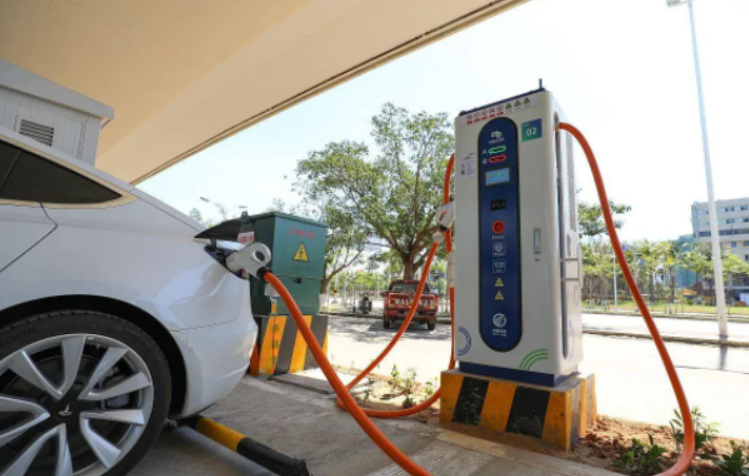
The expansion of electric vehicle charging networks has created a demanding materials problem. An electric vehicle charging pile is exposed to solar heating, nighttime cooling, rain, humidity, de-icing salts, airborne dust, mechanical vibration, accidental impact, and, in some installations, repeated freeze-thaw cycles. The structural material must therefore combine stiffness, strength, toughness, corrosion resistance, electrical insulation where required, and dimensional stability. Carbon-fiber-reinforced polymer composites are attractive for electric vehicle charging infrastructure because they offer high specific strength and specific stiffness, low weight, and good environmental resistance. Nylon 66 is particularly suitable as a thermoplastic matrix because it has a high melting point, good mechanical strength, reasonable abrasion resistance, and established melt-processing routes. However, the mechanical performance of carbon-fiber-reinforced nylon 66 is not a simple monotonic function of fiber content. Fiber length retention, fiber orientation, interfacial adhesion, matrix crystallinity, and fiber dispersion all interact. These interactions are especially important in electric vehicle charging pile components, where a material may need to resist a sudden impact without becoming excessively brittle.
I focused on three unresolved issues. First, the synergistic mechanism between nylon 66 and carbon fiber is not fully described by a simple rule-of-mixtures argument, because the presence of fiber alters crystallization and the effective load-transfer length. Second, the influence of fiber content on impact toughness is nonlinear and can exhibit a maximum. Third, electric vehicle charging piles require a design window rather than a single optimum property, because tensile strength, flexural stiffness, and impact energy absorption do not all peak at the same fiber content. My objective was therefore to establish a processing-structure-property relationship for continuous-fiber-fed melt-compounded nylon 66 composites and to identify the composition that gives the best comprehensive mechanical performance for electric vehicle charging pile applications.
2. Materials and Experimental Design
I used industrial-grade nylon 66 with a density of 1.129 g/cm3 as the matrix. The reinforcement was industrial-grade carbon fiber with a density of 1.76 g/cm3 and a specified tensile strength of 3,590 MPa. A silane coupling agent, KH-560, was used to improve interfacial compatibility, and a self-prepared compatibilizer was used to promote stress transfer between the carbon fiber and the nylon 66 matrix. The composites were prepared in a two-stage process. First, nylon 66, the silane coupling agent, and the compatibilizer were mixed in a cylindrical mixer. Second, the mixture was melt-compounded in a twin-screw extruder with continuous fiber feeding. The screw speed was set to 300 r/min. Carbon fiber was introduced at the feed port as one, two, or four bundles, with each bundle containing 12,000 filaments. The resulting materials are denoted CF0, CF1, CF2, and CF4, where CF0 is unfilled nylon 66 and the number indicates the number of carbon-fiber bundles.
I characterized the microstructure by polarized light microscopy after crystallization treatment and by field-emission scanning electron microscopy of fracture surfaces. Fiber length was measured with image-analysis software. Tensile tests were performed on a computer-controlled universal testing machine at a tensile rate of 5 mm/min. Flexural tests were performed at a flexural rate of 2 mm/min. Impact tests were performed on a dynamic impact analyzer using notched specimens with dimensions of 8 mm by 4 mm by 80 mm and a notch depth of 2 mm. Each mechanical result was taken as the average of three specimens. The processing and testing parameters are summarized in Table 1.
| Parameter | Value or description | Role in the study |
|---|---|---|
| Matrix | Industrial nylon 66, density 1.129 g/cm3 | Thermoplastic load-bearing matrix |
| Reinforcement | Carbon fiber, density 1.76 g/cm3, tensile strength 3,590 MPa | High-modulus reinforcing phase |
| Coupling agent | KH-560 silane | Interfacial compatibility |
| Compatibilizer | Self-prepared | Stress transfer and dispersion |
| Compounding equipment | Twin-screw extruder | Continuous fiber feeding and melt blending |
| Screw speed | 300 r/min | Mixing intensity and fiber length retention |
| Fiber bundles | 0, 1, 2, and 4 bundles | Composition variable |
| Filaments per bundle | 12,000 | Fiber-count scaling |
| Tensile rate | 5 mm/min | Tensile response |
| Flexural rate | 2 mm/min | Flexural response |
| Impact specimen | 8 mm by 4 mm by 80 mm, notch depth 2 mm | Notched impact toughness |
| Replicate count | 3 specimens per condition | Mean mechanical response |
The composition variable can be expressed in terms of the number of bundles. If nb is the number of bundles, Nf is the number of filaments per bundle, Af is the cross-sectional area of one filament, Lf is the mean fiber length, and rhof is the fiber density, the fiber mass in a representative volume is proportional to the number of bundles. I used the following relation to express the nominal fiber mass fraction:
$$
w_f = \frac{n_b N_f A_f L_f \rho_f}{n_b N_f A_f L_f \rho_f + m_m}
$$
where m_m is the matrix mass in the same representative volume. The corresponding fiber volume fraction is obtained from the densities of the fiber and matrix:
$$
V_f = \frac{w_f/\rho_f}{w_f/\rho_f + (1-w_f)/\rho_m}
$$
This conversion is important because mechanical models are usually written in terms of volume fraction, while the experimental variable in my process was the number of fed bundles. Because fiber length decreased as the number of bundles increased, the effective volume fraction and the effective aspect ratio did not scale identically. I therefore treated bundle count as a processing variable and fiber aspect ratio as a structure variable.
3. Theoretical Framework
I used several standard composite-mechanics expressions as interpretive tools rather than as fitting exercises. The first is the rule of mixtures for stiffness, modified by fiber-length and orientation factors:
$$
E_c = \eta_0 \eta_L V_f E_f + V_m E_m
$$
Here E_c is the composite modulus, E_f is the fiber modulus, E_m is the matrix modulus, V_m is the matrix volume fraction, eta0 is an orientation factor, and etaL is a fiber-length efficiency factor. For aligned short fibers, the length efficiency can be approximated by the Cox shear-lag expression:
$$
\eta_L = 1 – \frac{\tanh(\beta L_f/2)}{\beta L_f/2}
$$
where the shear-lag parameter is:
$$
\beta = \sqrt{\frac{2G_m}{E_f r_f^2 \ln(R/r_f)}}
$$
In this expression G_m is the matrix shear modulus, r_f is the fiber radius, and R is the effective radius of the matrix cylinder surrounding the fiber. The practical meaning is that longer fibers and stronger interfacial shear transfer increase etaL. In my composites, fiber length decreased with increasing bundle count, so the reinforcement efficiency per unit fiber volume was not constant. This is one reason why a simple linear extrapolation from CF0 to CF4 would be misleading.
For tensile strength, I used a modified rule-of-mixtures form:
$$
\sigma_c = \eta_s V_f \sigma_f + V_m \sigma_m
$$
where sigma_c is composite tensile strength, sigma_f is fiber strength, sigma_m is matrix strength, and etas is a strength-efficiency factor. For short-fiber composites, the Kelly-Tyson framework provides a more detailed decomposition:
$$
\sigma_c = \chi_1 \sum_i V_{f,i} \sigma_{f,i} + \sigma_m V_m
$$
where chi1 accounts for fiber orientation and length distribution and the sum is taken over fiber populations with different effective lengths. I did not attempt to determine every parameter independently, but I used these expressions to interpret the observed monotonic increase in tensile strength and the simultaneous decrease in elongation at break. The increase in strength is consistent with increased load sharing by the carbon fiber. The decrease in elongation is consistent with the reduced ductility of the matrix-rich regions and the progressive suppression of plastic flow around stiff inclusions.
For flexural response, I considered both strength and modulus because electric vehicle charging pile components are often stiffness-controlled. The flexural modulus of a short-fiber composite can be approximated by a Halpin-Tsai form:
$$
\frac{E_c}{E_m} = \frac{1+\xi \eta V_f}{1-\eta V_f}
$$
with
$$
\eta = \frac{E_f/E_m-1}{E_f/E_m+\xi}
$$
where xi is a geometry factor related to fiber aspect ratio and loading direction. This expression predicts that increasing fiber content raises modulus, but the rate of increase depends on aspect ratio and dispersion. The observed increase in flexural modulus with bundle count is therefore consistent with the reinforcing role of carbon fiber, while the reduced fiber length at higher bundle count limits the theoretical gain.
For impact toughness, I used an energy-integral description:
$$
U_c = \int_0^{\delta_f} F(\delta)\,d\delta
$$
where U_c is the absorbed impact energy, F is the force, delta is displacement, and delta_f is the displacement at final fracture. Impact toughness is not controlled by stiffness alone. It depends on the initiation and propagation of damage, the ability of the matrix to deform, the fiber-matrix interfacial strength, fiber pull-out, and the presence of agglomerates or voids. A useful geometric indicator is the mean fiber spacing. For a hexagonal arrangement, the critical spacing can be written as:
$$
s_c = \frac{\pi d_f}{2\sqrt{3}V_f} – d_f
$$
where d_f is the fiber diameter. As V_f increases, s_c decreases. A smaller spacing improves stress transfer but also increases the probability of fiber-fiber interaction and agglomeration. The impact maximum at two bundles is therefore interpreted as the point at which the positive effects of load sharing and crack deflection balance the negative effects of constrained matrix deformation and defect formation.
I also used crystallinity as a link between fiber content and matrix behavior. The crystallinity was estimated from the melting enthalpy:
$$
X_c = \frac{\Delta H_m}{\Delta H_m^0(1-w_f)} \times 100\%
$$
where DeltaH_m is the measured melting enthalpy of the composite, DeltaH_m0 is the melting enthalpy of fully crystalline nylon 66, and the denominator corrects for the non-crystalline fiber mass. The carbon fiber surface can act as a nucleation site, but it also reduces the matrix volume fraction and can restrict polymer chain mobility. The competition between these effects explains why the crystallization morphology changed after fiber addition and why the fiber length was affected by the compounding history.
| Symbol | Meaning | Interpretive relevance |
|---|---|---|
| Vf | Fiber volume fraction | Primary reinforcement variable |
| Vm | Matrix volume fraction | Ductility and matrix-mediated toughening |
| Lf | Mean fiber length | Load-transfer efficiency |
| df | Fiber diameter | Aspect ratio and spacing |
| alpha | Fiber aspect ratio | Short-fiber reinforcement quality |
| etaL | Length efficiency factor | Penalty for finite fiber length |
| etas | Strength efficiency factor | Orientation, length, and interface |
| Xc | Crystallinity | Matrix stiffness, yield, and embrittlement |
| Uc | Impact energy | Toughness metric |
| sc | Mean fiber spacing | Dispersion and agglomeration indicator |
4. Results and Discussion
4.1 Microstructure and Fiber Length
Microscopic observation after crystallization treatment showed that unfilled nylon 66 developed a spherulitic morphology, whereas all carbon-fiber-containing composites showed distributed carbon fibers and no obvious spherulitic morphology under the same treatment. This indicates that carbon fiber changes the crystallization attribute of nylon 66. I interpret this as a combined effect of nucleation, restricted chain mobility, and the reduction in matrix volume fraction. The presence of fiber surfaces can promote nucleation at low fiber content, but at higher fiber content the growth of large spherulites is geometrically restricted. The resulting crystalline texture is finer and less optically continuous than that of unfilled nylon 66.
Fiber length decreased as the number of bundles increased. The mean fiber length was approximately 0.66 mm for CF1, 0.58 mm for CF2, and 0.53 mm for CF4. This trend is physically reasonable. At a fixed screw speed and fixed compounding energy, a higher number of fiber bundles increases fiber-fiber interaction, fiber breakage, and the probability of repeated bending and buckling in the melt. The matrix also experiences a higher effective viscosity, which increases local shear. The result is a reduction in retained fiber length. The aspect ratio is:
$$
\alpha = \frac{L_f}{d_f}
$$
Because Lf decreases with increasing bundle count, the nominal benefit of adding more fiber is partially offset by a lower aspect ratio. This is a key reason why the impact response is non-monotonic even though stiffness and strength continue to increase.
| Material | Bundle count | Mean fiber length | Observed fiber distribution | Microstructural interpretation |
|---|---|---|---|---|
| CF0 | 0 | Not applicable | Spherulitic matrix | Matrix-dominated crystallization |
| CF1 | 1 | 0.66 mm | Uniform fiber dispersion | High length retention and good reinforcement potential |
| CF2 | 2 | 0.58 mm | Uniform fiber dispersion with local interactions | Balanced reinforcement and toughening |
| CF4 | 4 | 0.53 mm | More frequent fiber-fiber contacts | Higher stiffness but greater agglomeration risk |
The fracture surfaces supported this interpretation. Unfilled nylon 66 exhibited a relatively smooth fracture surface, which is characteristic of a matrix-dominated thermoplastic fracture. In contrast, all fiber-containing composites exhibited rougher surfaces with visible fiber breakage and local fiber pull-out. The matrix appeared to wet the fibers, and no obvious large voids or interfacial cracks were observed. This suggests that the coupling agent and compatibilizer promoted a useful level of interfacial adhesion. At the same time, the presence of pull-out indicates that the interfacial shear strength was not so high that all fibers fractured exactly at the crack plane. A finite pull-out length is beneficial for impact energy absorption because it contributes frictional work. However, excessive pull-out or poor dispersion would reduce the efficiency of stress transfer.
4.2 Crystallization and Matrix State
The disappearance of the spherulitic morphology after fiber addition does not mean that the matrix became amorphous. It means that the optical scale and continuity of the crystalline structure changed. Carbon fiber can increase the crystallization temperature by providing heterogeneous nucleation sites, but it also reduces the amount of matrix available for spherulitic growth and restricts segmental mobility near the interface. In my composites, the balance of these effects produced a finer crystalline texture. This has two consequences for electric vehicle charging applications. First, a finer crystalline texture can reduce large-scale strain localization and improve dimensional stability under thermal cycling. Second, a higher or more constrained crystalline state can reduce ductility, which is consistent with the observed decrease in elongation at break.
I use the following normalized crystallinity index to compare the matrix state across compositions:
$$
X_{c,n} = \frac{X_c}{X_{c,CF0}}
$$
where Xc,CF0 is the crystallinity of unfilled nylon 66. Although the absolute crystallinity depends on the thermal history, the normalized index is useful for ranking. The presence of fiber increases the heterogeneity of the matrix state: regions near the fiber surface may be more constrained, while regions far from the fiber may retain more mobile amorphous chains. This heterogeneous matrix state is beneficial for balancing stiffness and toughness up to a point, but at high fiber content the constrained fraction becomes dominant and the composite becomes more brittle.
| Composition | Spherulitic morphology | Matrix constraint | Expected effect on stiffness | Expected effect on ductility |
|---|---|---|---|---|
| CF0 | Clearly present | Low | Baseline | Highest elongation |
| CF1 | Not obvious | Moderate | Increased | Steep reduction |
| CF2 | Not obvious | Moderate to high | Further increased | Low but acceptable |
| CF4 | Not obvious | High | Highest | Lowest |
4.3 Tensile Behavior
Tensile strength increased with carbon-fiber content. This is the expected consequence of load sharing by a high-strength fiber phase. The increase was not perfectly linear because fiber length decreased and fiber-fiber interactions increased at higher bundle count. Nevertheless, the reinforcing effect remained dominant over the range I studied. The elongation at break showed the opposite trend. The largest drop occurred when the first bundle of carbon fiber was introduced. This sharp transition reflects the change from a ductile matrix-controlled deformation mode to a constrained composite deformation mode. Once the composite already contains a connected or semi-connected reinforcing network, additional fiber produces a smaller relative change in elongation, so the curve flattens.
I summarize the tensile response using three quantities. The first is the tensile strength:
$$
\sigma_t = \frac{F_{\max}}{A_0}
$$
where Fmax is the maximum tensile force and A0 is the original cross-sectional area. The second is the elongation at break:
$$
\varepsilon_b = \frac{L_b-L_0}{L_0} \times 100\%
$$
where L0 is the initial gauge length and Lb is the gauge length at break. The third is the tensile modulus obtained from the initial linear region:
$$
E_t = \frac{\Delta \sigma}{\Delta \varepsilon}
$$
The simultaneous increase in sigma_t and decrease in epsilon_b is a classic stiffness-toughness trade-off. For electric vehicle charging pile design, this trade-off must be interpreted together with the impact data. A material with high tensile strength but very low elongation may be undesirable in a component that experiences accidental impact or vibration-induced fatigue. This is why I do not select CF4 solely on the basis of tensile strength.
| Composition | Tensile strength trend | Elongation at break trend | Mechanistic interpretation | Design implication |
|---|---|---|---|---|
| CF0 | Baseline | Highest | Ductile matrix deformation | Good energy absorption but low stiffness |
| CF1 | Increased | Sharp decrease | Fiber constraint and load sharing begin | Improved strength with reduced ductility |
| CF2 | Further increased | Low | Balanced fiber network | Best combined tensile-impact profile |
| CF4 | Highest | Lowest | Fiber-dominated response and agglomeration risk | High stiffness but reduced damage tolerance |
4.4 Flexural Behavior
Flexural strength and flexural modulus both increased with carbon-fiber content. For unfilled nylon 66, the flexural strength was 89.2 MPa and the flexural modulus was 2,869 MPa. After carbon fiber was introduced, both properties increased, and the highest values were observed at the highest fiber content. This monotonic trend is easier to explain than the impact trend because flexural properties are strongly controlled by the axial stiffness and strength of the fiber phase. Carbon fiber acts as a load-bearing skeleton within the matrix. Under bending, the fibers on the tensile side carry a large fraction of the applied load, while the matrix transfers shear between fibers and stabilizes the fiber network.
I used the following definitions for flexural strength and modulus:
$$
\sigma_f = \frac{3FL}{2bd^2}
$$
and
$$
E_f = \frac{L^3 m}{4bd^3}
$$
where F is the maximum load, L is the support span, b is the specimen width, d is the specimen thickness, and m is the slope of the load-displacement curve in the linear region. The exact test geometry is fixed by the apparatus, but the scaling shows why fiber content has a strong effect. The flexural modulus is proportional to the slope of the load-displacement curve, and a stiff fiber network increases that slope. The flexural strength increases because the composite can sustain a higher maximum load before the tensile side fails or before compressive buckling occurs.
The increase in flexural properties is beneficial for electric vehicle charging pile enclosures and brackets, which often need to resist wind load, snow load, or accidental static loading. However, the flexural data alone could lead a designer to choose CF4. My impact data show why that choice would be incomplete. A charging pile component with very high flexural stiffness but low impact toughness may fail in a brittle manner under a localized hit, such as a vehicle contact, tool drop, or vandalism event. The optimal material for electric vehicle charging must therefore satisfy a multi-property criterion.
| Composition | Flexural strength | Flexural modulus | Relative stiffness trend | Engineering comment |
|---|---|---|---|---|
| CF0 | 89.2 MPa | 2,869 MPa | Baseline | Ductile but insufficiently stiff for highly loaded parts |
| CF1 | Higher than CF0 | Higher than CF0 | Increased | Useful for moderately loaded electric vehicle charging parts |
| CF2 | Higher than CF1 | Higher than CF1 | Further increased | Best balance of stiffness and impact toughness |
| CF4 | Highest | Highest | Maximum | Preferred only when stiffness dominates and impact risk is low |
4.5 Impact Behavior
The impact results were the most distinctive part of my study. Unfilled nylon 66 had a room-temperature impact strength of 8.47 kJ/m2. As carbon-fiber content increased, impact strength first increased and then decreased. The maximum value was 16.15 kJ/m2 at two bundles. This is a substantial improvement over the unfilled matrix, but it is not the highest fiber content. The existence of a maximum is important because it shows that carbon fiber can toughen nylon 66 up to a point, but beyond that point the composite becomes more defect-sensitive.
Several mechanisms contribute to the initial increase in impact strength. First, carbon fibers can deflect cracks and increase the tortuosity of the fracture path. Second, fiber pull-out consumes energy through friction and matrix deformation. Third, the constrained matrix region near the fiber can redistribute stress and delay the onset of unstable crack growth. Fourth, a well-dispersed fiber network can bridge the crack wake and carry load after local matrix failure. These mechanisms are most effective when the fiber content is high enough to create a connected reinforcement network but not so high that agglomeration and fiber-fiber contact dominate.
At four bundles, the negative effects become more important. The probability of fiber agglomeration increases. Agglomerates act as stress concentrators and can initiate cracks. The matrix volume fraction decreases, so there is less ductile matrix available to absorb energy. Fiber length also decreases, which reduces the pull-out length and the efficiency of crack bridging. The mean fiber spacing becomes smaller, which restricts matrix deformation between fibers. All of these effects reduce the energy absorbed before fracture. The net result is that the impact strength at CF4 is lower than that at CF2, even though tensile strength and flexural modulus are higher.
I describe the impact trend with a simple quadratic model:
$$
U_i = a n_b^2 + b n_b + c
$$
where Ui is the impact strength and nb is the number of bundles. The model is not intended to predict the entire composition space, but it captures the existence of an interior maximum. The maximum condition is:
$$
\frac{dU_i}{dn_b} = 2a n_b + b = 0
$$
and therefore:
$$
n_{b,\mathrm{opt}} = -\frac{b}{2a}
$$
In my data, n_b,opt lies at two bundles. The physical interpretation is that the positive toughening mechanisms scale with fiber content in the low-content regime, while the negative agglomeration and constraint mechanisms become dominant in the high-content regime. This is exactly the kind of non-monotonic behavior that must be captured in a design-oriented material model for electric vehicle charging piles.
| Composition | Impact strength | Dominant toughening mechanism | Dominant degradation mechanism | Overall assessment |
|---|---|---|---|---|
| CF0 | 8.47 kJ/m2 | Matrix plastic deformation | Low stiffness | Ductile but under-reinforced |
| CF1 | Higher than CF0 | Crack deflection and initial fiber bridging | Reduced matrix ductility | Improved toughness |
| CF2 | 16.15 kJ/m2 | Balanced bridging, pull-out, and matrix constraint | Moderate agglomeration risk | Optimum impact toughness |
| CF4 | Lower than CF2 | High fiber load sharing | Agglomeration and reduced matrix volume | Highest stiffness but reduced toughness |
4.6 Fracture Morphology and Interfacial Synergy
The fracture surfaces provided direct evidence for the proposed mechanisms. Unfilled nylon 66 showed a relatively smooth fracture surface, consistent with a matrix-dominated fracture process. The fiber-containing composites showed rougher surfaces with fiber breakage, fiber pull-out, and matrix debris. The roughness increased with fiber content up to the point where agglomeration became significant. The presence of fiber pull-out is especially important for impact energy absorption. When a fiber is pulled out, the interface must debond and then slide, which dissipates energy. If the interface is too strong, the fiber fractures instead of pulling out, which reduces the frictional contribution. If the interface is too weak, the fiber debonds prematurely and carries little load. The coupling agent and compatibilizer therefore need to produce an intermediate interfacial strength.
I define an interfacial synergy index as the ratio of the measured composite property to the property predicted by a simple additive rule:
$$
S_p = \frac{P_c}{P_m V_m + P_f V_f}
$$
where P is the property of interest, P_c is the composite property, P_m is the matrix property, and P_f is the fiber property. A value of S_p greater than one indicates positive synergy, while a value below one indicates a penalty. For tensile strength and flexural modulus, S_p is expected to be positive because the fiber carries load. For impact strength, S_p can be greater than one at intermediate fiber content because the fiber adds toughening mechanisms that are not present in either constituent alone. At high fiber content, S_p can decrease because agglomeration and constrained matrix deformation reduce the efficiency of the reinforcement.
| Microstructural feature | Observation | Mechanical consequence | Design relevance |
|---|---|---|---|
| Matrix fracture | Smooth in CF0 | High ductility but low stiffness | Baseline for comparison |
| Fiber breakage | Visible in CF1, CF2, CF4 | Direct load carrying by fibers | Increases tensile and flexural strength |
| Fiber pull-out | Local in all fiber composites | Frictional energy absorption | Contributes to impact toughness |
| Interfacial wetting | Fibers covered by matrix | Effective stress transfer | Reduces premature debonding |
| Agglomeration | More likely at CF4 | Stress concentration and crack initiation | Limits impact toughness |
4.7 Composition-Property Mapping
The combined data show that no single composition is optimal for every property. CF4 is best for tensile strength and flexural stiffness. CF2 is best for impact toughness and gives a strong tensile and flexural response. CF1 is useful when a moderate property increase is needed with less fiber loading. CF0 remains the most ductile but is insufficiently stiff for many structural electric vehicle charging pile applications. I therefore define a composite performance index for electric vehicle charging pile materials:
$$
Q = w_1 \frac{\sigma_t}{\sigma_{t,0}} + w_2 \frac{E_f}{E_{f,0}} + w_3 \frac{U_i}{U_{i,0}}
$$
where Q is the normalized performance index, sigma_t is tensile strength, E_f is flexural modulus, U_i is impact strength, the subscript zero denotes the unfilled matrix, and w1, w2, and w3 are weighting factors chosen according to the application. For a charging pile enclosure that must resist accidental impact and wind load, I would assign a relatively high weight to impact strength and a moderate weight to flexural modulus. For a support bracket that is stiffness-controlled and protected from impact, I would assign a higher weight to flexural modulus.
Using equal weights as a neutral baseline, the two-bundle composite provides the best balance because it combines a substantial increase in tensile strength, a significant increase in flexural modulus, and the maximum impact strength. The four-bundle composite has higher stiffness and strength but a lower impact value. This is the central design conclusion of my study.
| Composition | Tensile strength rank | Flexural modulus rank | Impact strength rank | Balanced performance rank |
|---|---|---|---|---|
| CF0 | 4 | 4 | 4 | 4 |
| CF1 | 3 | 3 | 2 | 3 |
| CF2 | 2 | 2 | 1 | 1 |
| CF4 | 1 | 1 | 3 | 2 |
5. Implications for Electric Vehicle Charging Infrastructure
The material selection logic for electric vehicle charging piles differs from that for a simple laboratory coupon. A charging pile is a system of enclosures, mounting brackets, cable-management parts, internal supports, and protective covers. Each component has a different load case. An enclosure may be dominated by impact and weather resistance. A bracket may be dominated by flexural stiffness. A support may be dominated by tensile strength and creep resistance. My results therefore support a graded material strategy rather than a single universal composition. CF2 is the best general-purpose choice for electric vehicle charging components that must survive occasional impact. CF4 is suitable for highly stiffness-critical parts that are protected from direct impact. CF1 is suitable for parts where a moderate increase in stiffness is needed without a large increase in fiber loading.
The electric vehicle charging environment also includes temperature cycling. Nylon 66 is semicrystalline, and its properties depend on temperature and moisture. Carbon fiber reduces the thermal expansion coefficient and increases dimensional stability, which is beneficial for outdoor electric vehicle charging equipment. However, the matrix remains sensitive to moisture and temperature. The fiber-matrix interface must remain stable under hygrothermal cycling. The silane coupling agent and compatibilizer used in my process are intended to improve this stability, but long-term aging under combined temperature, humidity, and mechanical load remains an important topic for future work.
Vibration is another relevant load case. Electric vehicle charging piles may experience vibration from nearby traffic, cooling fans, relays, and cable movement. Carbon fiber increases stiffness, which can shift natural frequencies away from excitation frequencies. However, increased stiffness can also reduce damping. A two-bundle composite may offer a better compromise than a four-bundle composite because it retains a higher matrix volume fraction and therefore more intrinsic damping. This hypothesis is consistent with the impact results, which show that CF2 has the best energy absorption among the fiber-containing composites.
| Electric vehicle charging component | Dominant requirement | Recommended composition | Reason |
|---|---|---|---|
| Outer enclosure | Impact resistance and weather stability | CF2 | Highest impact strength with useful stiffness |
| Mounting bracket | Flexural stiffness and strength | CF4 or CF2 | CF4 maximizes stiffness; CF2 improves damage tolerance |
| Internal support | Tensile strength and dimensional stability | CF4 | Highest tensile and flexural values |
| Cable guide | Moderate stiffness and toughness | CF1 or CF2 | Balanced property increase without excessive brittleness |
| Protective cover | Impact and vibration damping | CF2 | Best impact energy absorption |
6. Design Window and Quantitative Selection Criterion
I propose a quantitative selection criterion for electric vehicle charging pile composites. The criterion combines normalized tensile strength, normalized flexural modulus, and normalized impact strength:
$$
\Phi = \alpha_1 \left(\frac{\sigma_t}{\sigma_{t,CF0}}\right) + \alpha_2 \left(\frac{E_f}{E_{f,CF0}}\right) + \alpha_3 \left(\frac{U_i}{U_{i,CF0}}\right)
$$
subject to
$$
\frac{U_i}{U_{i,CF0}} \geq U_{\min}
$$
and
$$
\frac{\sigma_t}{\sigma_{t,CF0}} \geq S_{\min}
$$
where Phi is the selection score, alpha1, alpha2, and alpha3 are application weights, U_min is the minimum acceptable normalized impact strength, and S_min is the minimum acceptable normalized tensile strength. For a general electric vehicle charging enclosure, I would choose U_min greater than or equal to 1.5 and S_min greater than or equal to 1.2. Under these constraints, CF2 is the preferred composition because it gives the highest impact strength while still providing a clear increase in tensile and flexural properties. CF4 would be preferred only if the stiffness weight alpha2 is dominant and the impact constraint is relaxed.
The design window can be visualized as an interval in bundle count. The lower bound is set by the minimum stiffness and strength required for the component. The upper bound is set by the minimum impact toughness and the maximum acceptable processing difficulty. In my data, the lower bound is above zero bundles because unfilled nylon 66 is insufficiently stiff. The upper bound is below four bundles for impact-critical parts because CF4 has lower impact strength than CF2. The resulting window is:
$$
1 \leq n_b \leq 4
$$
for stiffness-dominated parts, and
$$
n_b \approx 2
$$
for impact-critical electric vehicle charging parts. This is a simple but useful design rule. It states that the carbon-fiber content should not be selected by maximizing a single property. Instead, it should be selected by matching the property profile to the dominant failure mode of the component.
| Design scenario | Dominant failure mode | Preferred composition | Supporting evidence |
|---|---|---|---|
| Impact-critical enclosure | Localized accidental impact | CF2 | Maximum impact strength of 16.15 kJ/m2 |
| Stiffness-critical bracket | Flexural deflection | CF4 | Highest flexural strength and modulus |
| Strength-critical support | Tensile overload | CF4 | Highest tensile strength trend |
| Balanced structural part | Mixed load and impact | CF2 | Best combined mechanical profile |
| Moderate reinforcement | Low-to-medium load | CF1 | Property increase with lower fiber loading |
7. Mechanistic Interpretation of the Two-Bundle Optimum
The two-bundle optimum can be understood as a balance among four length scales. At the molecular scale, the carbon fiber surface alters the crystallization and chain mobility of nylon 66. At the fiber scale, the aspect ratio controls stress transfer. At the bundle scale, dispersion and agglomeration control defect formation. At the component scale, the fiber network controls stiffness and crack bridging. The two-bundle composite is the point at which these scales cooperate most effectively. The fiber content is high enough to form a reinforcing network and to activate crack deflection and pull-out, but it is not so high that fiber-fiber contact and agglomeration dominate. The matrix volume fraction is still sufficient to provide ductility and energy absorption. The fiber length is still high enough to provide an effective aspect ratio. These factors together produce the maximum impact strength.
I can express the competition between reinforcement and embrittlement using a simple balance equation:
$$
U_i = U_{\mathrm{bridging}} + U_{\mathrm{pullout}} + U_{\mathrm{matrix}} – U_{\mathrm{agglomeration}}
$$
where U_bridging is the energy associated with crack bridging, U_pullout is the frictional pull-out energy, U_matrix is the matrix deformation energy, and U_agglomeration is the energy penalty associated with agglomerates and stress concentrations. As fiber content increases, U_bridging and U_pullout increase, but U_matrix decreases and U_agglomeration increases. The maximum occurs when the positive terms increase more slowly than the negative terms. This balance is consistent with the observed transition from CF2 to CF4.
A similar balance applies to stiffness and strength. The stiffness is dominated by the fiber phase and increases monotonically. The strength increases because the fiber carries load, but the rate of increase is limited by fiber length degradation. The elongation decreases because the matrix volume fraction and the mobile amorphous fraction decrease. These trends are not independent. They are coupled through the same microstructure. This is why a single parameter such as fiber weight fraction is insufficient for design. The processing history, which controls fiber length and dispersion, must be included in the material specification.
8. Practical Processing Considerations
Continuous-fiber-fed melt compounding is a practical route for producing carbon-fiber-reinforced nylon 66 for electric vehicle charging components because it can be integrated with conventional thermoplastic processing. However, the process window is narrow. A high screw speed improves dispersion but increases fiber breakage. A low screw speed preserves fiber length but may produce incomplete mixing. The feed arrangement must prevent fiber bundles from entering the melt as large agglomerates. The coupling agent and compatibilizer must be selected to match the fiber surface chemistry and the nylon 66 end-group chemistry. The drying history of nylon 66 is also important because moisture can cause hydrolysis and reduce mechanical performance.
I recommend three processing controls for electric vehicle charging applications. First, the fiber length after compounding should be monitored as a quality-control parameter. A decrease in fiber length below a critical value reduces both strength and impact toughness. Second, the dispersion state should be inspected on fracture surfaces or polished sections. Large agglomerates should be avoided even if the average fiber content is correct. Third, the crystallization and moisture state should be controlled because both affect the ductile-to-brittle transition. These controls are especially important for electric vehicle charging piles, which are safety-related infrastructure components.
| Processing variable | Positive effect of increase | Negative effect of increase | Recommended control |
|---|---|---|---|
| Screw speed | Better dispersion | More fiber breakage | Optimize for length retention and dispersion |
| Fiber bundle count | Higher stiffness and strength | Agglomeration and reduced impact toughness | Use two bundles for impact-critical parts |
| Coupling agent | Improved interfacial shear strength | Excessive brittleness if interface is too strong | Target intermediate interfacial strength |
| Moisture content | Improved ductility up to a point | Hydrolysis and property degradation | Dry before processing and control service humidity |
9. Limitations and Future Work
My study has several limitations that should be addressed before large-scale deployment in electric vehicle charging infrastructure. First, the mechanical tests were performed at room temperature. Electric vehicle charging piles experience a wide temperature range, including summer solar heating and winter freezing. The ductile-to-brittle transition of nylon 66 is temperature-sensitive, so the impact optimum may shift at low temperature. Second, the tests did not include long-term hygrothermal aging. Moisture absorption can plasticize the matrix and weaken the interface. Third, the study did not include fatigue testing under combined mechanical and thermal cycling. Fourth, the fiber orientation in actual injection-molded components may differ from that in the test specimens. Flow-induced orientation can create anisotropic properties that are not captured by uniaxial coupon tests.
Future work should therefore include four extensions. The first is a temperature-dependent impact study covering the range relevant to outdoor electric vehicle charging. The second is a hygrothermal aging study with periodic mechanical testing. The third is a fatigue and vibration study on representative bracket geometries. The fourth is a multiscale modeling study that links fiber length distribution, dispersion, crystallinity, and fracture toughness. Such a model would allow the design window to be optimized for specific electric vehicle charging pile components rather than for a generic coupon.
I also see an opportunity to combine carbon fiber with other fillers. For example, a small addition of a toughening phase could offset the ductility loss at high fiber content. A hybrid fiber architecture could provide a better balance between stiffness and impact resistance. However, any hybrid design must preserve the processability and cost advantages of the continuous-fiber-fed melt compounding route. The two-bundle optimum identified in my study provides a useful baseline for such future development.
10. Conclusions
I prepared carbon-fiber-reinforced nylon 66 composites by continuous-fiber-fed melt compounding and evaluated their microstructure and mechanical performance for electric vehicle charging pile applications. The following conclusions summarize my findings.
First, carbon fiber changes the crystallization attribute of nylon 66. Unfilled nylon 66 shows a spherulitic morphology after crystallization treatment, whereas fiber-containing composites show a distributed fiber network without obvious spherulites. This change is caused by a combination of heterogeneous nucleation, restricted matrix mobility, and reduced matrix volume fraction.
Second, fiber length decreases with increasing bundle count. The mean fiber length is approximately 0.66 mm at one bundle, 0.58 mm at two bundles, and 0.53 mm at four bundles. This reduction in aspect ratio partially offsets the benefit of higher fiber content and contributes to the non-monotonic impact behavior.
Third, tensile strength increases with carbon-fiber content, while elongation at break decreases. The largest drop in elongation occurs when the first bundle is added. This reflects the transition from matrix-dominated ductile deformation to fiber-constrained composite deformation.
Fourth, flexural strength and flexural modulus increase monotonically with carbon-fiber content. The unfilled matrix has a flexural strength of 89.2 MPa and a flexural modulus of 2,869 MPa. Higher fiber content produces higher values because the carbon fiber acts as a load-bearing skeleton and increases the stiffness of the composite.
Fifth, impact strength is non-monotonic. It increases from 8.47 kJ/m2 for unfilled nylon 66 to a maximum of 16.15 kJ/m2 at two bundles, and then decreases at four bundles. The maximum is caused by a favorable balance between crack bridging, fiber pull-out, matrix deformation, and dispersion quality. At higher fiber content, agglomeration and reduced matrix volume dominate and reduce toughness.
Sixth, the two-bundle composite provides the best comprehensive mechanical performance for electric vehicle charging pile components that must resist impact. The four-bundle composite is preferred only for stiffness-critical parts that are protected from impact. The one-bundle composite is useful for moderate reinforcement. This graded selection strategy is more appropriate than a single universal composition.
Overall, my results establish a processing-structure-property relationship for carbon-fiber-reinforced nylon 66 in electric vehicle charging infrastructure. The work shows that the optimal fiber content depends on the dominant failure mode and that impact toughness can be maximized at an intermediate fiber content. These findings provide a practical basis for material selection, component design, and future development of high-reliability electric vehicle charging piles.
| Summary item | Key result | Design implication for electric vehicle charging |
|---|---|---|
| Crystallization | Fiber addition removes obvious spherulitic morphology | Improved dimensional stability but reduced matrix ductility |
| Fiber length | Decreases from 0.66 mm to 0.53 mm as bundles increase | Higher fiber loading has diminishing reinforcement efficiency |
| Tensile strength | Increases with fiber content | CF4 is preferred for strength-critical supports |
| Elongation at break | Decreases with fiber content | Ductility must be checked for impact and vibration loads |
| Flexural properties | Strength and modulus increase with fiber content | CF4 is preferred for stiffness-critical brackets |
| Impact strength | Maximum of 16.15 kJ/m2 at two bundles | CF2 is preferred for impact-critical enclosures |
| Balanced optimum | Two bundles give the best combined profile | Use CF2 as the general-purpose electric vehicle charging composite |
In my assessment, the most important outcome is not a single number but the coupling between composition and failure mode. Electric vehicle charging infrastructure requires materials that are stiff enough to resist service loads, strong enough to carry structural forces, and tough enough to survive accidental impact. Carbon-fiber-reinforced nylon 66 can meet these requirements, but only when the fiber content is selected within a design window. The two-bundle composition defines that window for impact-critical electric vehicle charging components, while the four-bundle composition defines the stiffness-oriented boundary. This dual-window concept is the main practical contribution of my study and provides a foundation for further optimization of electric vehicle charging pile materials.