
As a researcher deeply immersed in the field of automotive electrification, I have witnessed firsthand the transformative shift toward new energy vehicles (NEVs) driven by global environmental concerns and the pressing need for sustainable development. The electric drive system stands as the pivotal core of these vehicles, directly dictating their dynamic performance, energy efficiency, and overall reliability. In this comprehensive analysis, I will delve into the intricacies of the electric drive system, examining its composition, operational principles, key components, rigorous testing protocols, and potential failure modes. The aim is to provide a foundational reference that can inform future research and development efforts aimed at enhancing this critical technology. Throughout this discussion, the term ‘electric drive system’ will be frequently emphasized to underscore its centrality.
The evolution of the electric drive system has been remarkable, yet the journey is far from complete. To meet escalating market demands for longer range, higher power density, and superior cost-effectiveness, continuous and profound research into the electric drive system is indispensable. This article represents our systematic effort to consolidate current knowledge and explore the technical depths of the electric drive system.
Fundamental Overview of the Electric Drive System
At its heart, the modern electric drive system for vehicles is a highly integrated unit, often referred to as the “e-drive” or “e-axle.” It primarily consists of three major assemblies: the drive motor, the motor controller (inverter), and the gear reducer (differential). The synergistic operation of these components converts electrical energy from the battery into precise mechanical torque at the wheels.
The working principle is an elegant sequence of energy transformation. Upon driver input via the accelerator pedal, the vehicle controller sends a torque command. The motor controller, acting as the brain and muscle of the electric drive system, immediately converts the direct current (DC) from the high-voltage battery into alternating current (AC). This AC power is then supplied to the drive motor. Within the motor, the interaction between the magnetic fields generated in the stator and the rotor (or the induced currents in it) produces a rotational force. The motor outputs high-speed rotation, which is then fed into the gear reducer. The reducer’s role is crucial—it steps down the rotational speed while multiplying the torque, delivering an optimal combination of force and speed to the vehicle’s half-shafts and finally to the wheels, propelling the vehicle forward. The efficiency of this entire chain defines the performance of the electric drive system.
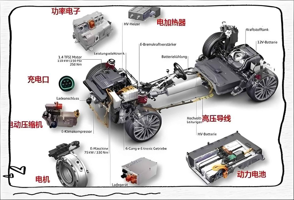
The trend in modern electric drive system design is toward deep integration. This “3-in-1” approach, where the motor, controller, and reducer share a common housing or are directly coupled, minimizes size, weight, and energy losses from interconnections, thereby boosting the power density of the overall electric drive system. The image above illustrates a typical integrated electric drive system module.
Detailed Examination of Key Components
1. The Drive Motor
The drive motor is the primary actuator within the electric drive system. Its design and type significantly influence efficiency, torque characteristics, and cost. The two predominant types in automotive applications are the Permanent Magnet Synchronous Motor (PMSM) and the AC Induction Motor (IM).
A PMSM, as shown in a typical cross-section, comprises a stator (with laminated steel core and three-phase windings), a rotor embedded with permanent magnets (often rare-earth magnets like Neodymium), a housing, end covers, a cooling jacket, and position/speed sensors. When three-phase AC is applied to the stator windings, it creates a rotating magnetic field. The permanent magnets on the rotor lock onto this rotating field, causing the rotor to spin synchronously. The torque production can be described by a simplified equation:
$$T_e = \frac{3}{2} p \left[ \psi_f I_q + (L_d – L_q) I_d I_q \right]$$
where \(T_e\) is the electromagnetic torque, \(p\) is the number of pole pairs, \(\psi_f\) is the permanent magnet flux linkage, \(I_d\) and \(I_q\) are the direct and quadrature axis currents, and \(L_d\), \(L_q\) are the corresponding inductances. PMSMs are favored for their high power density and excellent efficiency across a wide operating range, making them a cornerstone of modern electric drive systems.
In contrast, the AC Induction Motor operates on the principle of electromagnetic induction. The stator windings, when energized, create a rotating magnetic field. This field induces currents in the rotor’s conductive bars (squirrel-cage design), which in turn generate their own magnetic field. The interaction between the stator field and the induced rotor field produces torque. A key characteristic is slip (\(s\)), defined as:
$$s = \frac{n_s – n_r}{n_s}$$
where \(n_s\) is the synchronous speed of the stator field and \(n_r\) is the rotor speed. The torque-speed relationship is more complex and inherently involves slip. IMs are robust, lower in cost, and do not require rare-earth materials, but they generally offer lower peak efficiency compared to PMSMs.
Cooling is paramount for motor performance and longevity. Many electric drive systems employ oil-cooling, where oil is circulated directly over the stator windings and rotor, offering superior heat transfer compared to traditional water-jacket cooling. This allows for higher continuous power output from the same motor size.
| Motor Type | Key Advantages | Key Disadvantages | Typical Efficiency Range | Cost Factor |
|---|---|---|---|---|
| Permanent Magnet Synchronous Motor (PMSM) | High power & torque density, high peak efficiency, excellent controllability | Use of expensive rare-earth magnets, potential demagnetization at high temps | 95-97% | High |
| AC Induction Motor (IM) | Robust, simple construction, no permanent magnets, high maximum speed capability | Lower efficiency at light loads, requires more cooling for same power | 92-95% | Medium |
| Switched Reluctance Motor (SRM) | Very robust, low cost, can operate in high-temperature environments | High torque ripple, acoustic noise, more complex control required | 90-94% | Low-Medium |
2. The Motor Controller (Inverter)
The motor controller is the intelligent power converter of the electric drive system. It performs two critical functions: it regulates the power flow from the battery to the motor based on torque commands, and it precisely controls the motor’s speed and position through advanced algorithms.
Its core power stage consists of semiconductor switches, traditionally Insulated-Gate Bipolar Transistors (IGBTs) and increasingly Silicon Carbide (SiC) MOSFETs. These devices switch at high frequencies (often 5-20 kHz) to synthesize the variable-frequency, variable-amplitude AC waveform required by the motor. The basic voltage output for a three-phase inverter can be represented by space vector modulation techniques. The controller’s central processing unit, typically a high-performance microcontroller (MCU) or digital signal processor (DSP), executes field-oriented control (FOC) algorithms. FOC transforms the motor’s three-phase currents into a two-axis rotating reference frame (\(d\)-\(q\) axes), allowing for independent control of torque-producing current (\(I_q\)) and flux-producing current (\(I_d\)), much like controlling a DC motor. This is described by the Park and Clarke transformations:
$$I_{\alpha} = I_a$$
$$I_{\beta} = \frac{1}{\sqrt{3}} (I_a + 2I_b)$$
$$I_d = I_{\alpha} \cos(\theta) + I_{\beta} \sin(\theta)$$
$$I_q = -I_{\alpha} \sin(\theta) + I_{\beta} \cos(\theta)$$
where \(I_a, I_b\) are phase currents and \(\theta\) is the rotor electrical position. The precision of this control directly impacts the efficiency and dynamic response of the overall electric drive system.
Additional critical subsystems within the controller include gate driver circuits, DC-link capacitors, current/voltage/temperature sensors, and comprehensive protection circuits (over-current, over-voltage, over-temperature, short-circuit). The thermal management of the power module is often achieved via a cold plate integrated into the controller housing, through which coolant flows.
3. The Gear Reducer
Contrary to multi-speed transmissions in internal combustion vehicles, most electric drive systems utilize a single-speed fixed-ratio gear reducer. This is because electric motors provide high torque from zero speed and have a wide constant power range. The reducer’s purpose is to optimally match the motor’s high-speed, moderate-torque output to the low-speed, high-torque requirements at the wheels.
A typical reducer consists of a input pinion gear mounted on the motor shaft, a larger output ring gear (often integrating the differential), bearings, seals, and a housing filled with specialized lubricating oil. The fundamental relationship is given by:
$$T_{out} = T_{in} \times GR \times \eta_{gear}$$
$$n_{out} = \frac{n_{in}}{GR}$$
where \(T_{in}, T_{out}\) are input and output torques, \(n_{in}, n_{out}\) are input and output speeds, \(GR\) is the gear ratio (typically between 8:1 and 12:1 for passenger cars), and \(\eta_{gear}\) is the gear mesh efficiency (often >97%). The design focuses on minimizing noise, vibration, and harshness (NVH), maximizing efficiency, and ensuring durability. Advanced lubrication systems may include oil pumps for active cooling and lubrication of critical components under high-stress conditions.
Rigorous Testing Requirements for Electric Drive Systems
To ensure the reliability, safety, and performance of the electric drive system over the vehicle’s lifetime, a comprehensive suite of validation tests is conducted. These tests simulate and accelerate real-world operating conditions, environmental exposures, and mechanical stresses. The following table summarizes a core set of endurance and environmental tests that every electric drive system must undergo. It is through such rigorous validation that we can confidently assess the robustness of the electric drive system.
| Test Sequence | Test Item | Test Conditions & Procedure Summary | Pass/Fail Criteria |
|---|---|---|---|
| 1 | Motor Speed Cycle Endurance | The motor is subjected to continuous speed cycles from 0 to maximum base speed. Rotor temperature is maintained at a high level (e.g., 150°C) via controlled cooling. Acceleration/deceleration ramps last 20 seconds, with 1-second dwells at peak and zero speed. This cycle is repeated for a minimum of 30,000 iterations. | Post-test, the motor must maintain specified air-tightness and insulation resistance. Upon teardown, key components (bearings, windings, magnets) must show no unacceptable plastic deformation, cracks, or breaks. Operation must remain free of binding or abnormal noise. |
| 2 | Gear Reducer Shock (Peak Torque) Test | The reducer output is locked stationary. The input is subjected to a pulsed torque profile reaching 2 times the system’s maximum transmitted torque (Motor Max Torque × Gear Ratio). Each torque pulse cycle lasts 0.4 seconds. The test is run for a set number of cycles (e.g., 1,000) for validation, and often continued to failure for design margin analysis. | After the prescribed cycles, the gear teeth, shafts, and bearings are inspected for any signs of damage, pitting, or permanent deformation. The unit must not exhibit leaks. For margin tests, the number of cycles to failure is recorded. |
| 3 | Complete E-Drive System Driving Durability | The entire integrated electric drive system undergoes a prolonged dynamometer test simulating varied driving profiles. Test parameters include different voltage levels (simulating battery SOC), controlled coolant temperature (~65°C), and specified oil flow. The test profile includes urban, highway, and aggressive driving cycles, totaling hundreds of hours of operation. | Throughout the test, no abnormal power interruptions, hesitation, or unusual vibrations are permitted. Upon completion, disassembly reveals no critical wear or failure: no gear tooth fractures, bearing spalling, seal leakage, or insulation degradation. This test validates the lifecycle durability of the electric drive system. |
| 4 | Thermal Shock & Submersion (Ice Water Immersion) | This environmental stress test evaluates seal integrity and material resistance. The system is heated to a stable high temperature (e.g., 85°C) for 1 hour. While still hot and powered (under no-load), it is fully immersed in an ice-water bath (0°C) for 5 minutes. This drastic thermal cycle is repeated 10 times. The unit’s breather may be extended above water. | After cycling, the electric drive system must show no water ingress. Visual inspection reveals no cracks or deformities. Electrical tests confirm maintained insulation resistance and full functional operation. Analysis of the internal lubricant must show water content below a strict threshold (e.g., ≤ 5000 ppm). |
Beyond these, extensive NVH testing, electromagnetic compatibility (EMC) testing, efficiency mapping across all operating points, and software/controller functional safety tests (e.g., ISO 26262) are integral parts of developing a mature electric drive system.
Failure Mode and Effects Analysis (FMEA) for Electric Drive Systems
Proactively identifying potential failure points is crucial for designing a robust electric drive system. Based on field data and accelerated life testing, we can catalog common failure modes, their root causes, and typical effects. The following table synthesizes this knowledge for the key subsystems of the electric drive system. Understanding these failure modes guides our design improvements, material selection, and protective control strategies.
| Subsystem | Failure Mode | Potential Root Causes | Likely Effects on System/Vehicle |
|---|---|---|---|
| Drive Motor | Insulation Resistance Degradation / Short Circuit | Insufficient creepage and clearance distances; Thermal overstress causing insulation aging (Class H vs. Class F material mismatch); Contamination from coolant or foreign debris ingress due to poor sealing; Partial discharge over time. | Reduced efficiency, ground faults, phase-to-phase shorts leading to uncontrolled torque, complete system shutdown, or thermal runaway. |
| High-Temperature Burn-out of Lead Wires/Connections | Undersized cable cross-section for the required current, leading to excessive I²R heating; Use of cable insulation with an inadequate temperature rating for the hotspot location. | Localized overheating, melting of insulation, open circuit, arcing, potentially causing a fire hazard within the electric drive system. | |
| Permanent Magnet Demagnetization | Excessive operating temperature exceeding the magnet’s Curie point; High opposing magnetic fields from fault currents (e.g., during short-circuit events). | Permanent loss of motor torque and power, reduced efficiency, potential imbalance and vibration. | |
| Motor Controller | Power Semiconductor Failure (IGBT/SiC) | Thermal cycling fatigue leading to bond wire lift-off or solder fatigue; Over-voltage spikes (e.g., from load dump); Over-current due to motor short or extreme overload; Gate driver malfunction. | Catastrophic short circuit in the inverter, blowing fuses, loss of propulsion, possible damage to the DC-link capacitor. |
| DC-Link Capacitor Degradation | Electrolyte drying out due to high operating temperature; Excessive ripple current beyond specification; Voltage overstress. | Increased equivalent series resistance (ESR), reduced capacitance, leading to higher DC-link voltage ripple, controller instability, and ultimately open or short circuit failure. | |
| Cooling System Failure (Leak/Blockage) | Corrosion or mechanical failure of cooling channels; Particulate clogging in narrow micro-channel cold plates; Poor brazing or sealing. | Inadequate cooling of power modules, leading to rapid thermal runaway and destruction of semiconductors. This is a critical vulnerability for the electric drive system. | |
| Gear Reducer | Gear Tooth Pitting, Scoring, or Fracture | Surface fatigue under high cyclic contact stress; Inadequate lubrication (low oil level, wrong oil grade, degraded oil); Material defects or improper heat treatment leading to insufficient surface hardness. | Increased NVH (whine, growl), loss of efficiency, metal debris contaminating lubrication, and eventual catastrophic gear seizure or breakage, disabling the electric drive system. |
| Shaft Bearing Failure | Contamination (water, dirt); Lubrication starvation; False brinelling from vibration during transport; Excessive axial or radial loads beyond design. | High-pitched noise, increased rotational friction, vibration, increased temperature, and eventual bearing lock-up, which can seize the motor or break shafts. | |
| Input/Output Seal Leakage | Seal lip wear or hardening over time; Damage during assembly; Shaft surface finish degradation; Excessive internal pressure due to temperature swings. | Loss of lubricant leads to accelerated gear and bearing wear. Oil contamination of other components. Environmental contamination ingress. |
Mitigating these failures involves a multi-pronged approach: robust mechanical design with safety margins, careful material selection (e.g., high-temperature magnet wires, durable seal materials), advanced thermal management strategies, and sophisticated software protections within the controller that can detect anomalous conditions (like rising temperature, current imbalance, or insulation degradation) and take preventive action (derating torque, warning the driver, or performing a safe shutdown).
Advanced Topics and Future Directions
The pursuit of excellence in electric drive system technology is unending. Current research frontiers that we are actively exploring include:
Wide-Bandgap Semiconductors: The transition from Silicon IGBTs to Silicon Carbide (SiC) and Gallium Nitride (GaN) devices is revolutionizing the motor controller. These materials allow for much higher switching frequencies (100+ kHz), drastically reducing the size of passive components (inductors, capacitors) and cutting switching losses. The efficiency gain, especially at partial load, can be significant. The system-level impact is a more compact, cooler-running, and more efficient electric drive system. The efficiency improvement can be modeled by comparing power loss:
$$P_{loss, total} = P_{cond} + P_{sw} = I^2 R_{ds(on)} + \frac{1}{2} V_{ds} I (t_{rise}+t_{fall}) f_{sw}$$
Where SiC devices exhibit lower \(R_{ds(on)}\) and vastly superior switching times (\(t_{rise}, t_{fall}\)) compared to Si IGBTs, even at higher \(f_{sw}\).
Integrated Thermal Management: The next generation of electric drive systems is moving toward fully unified thermal systems. This involves using the vehicle’s refrigerant circuit (from the air conditioning system) to directly cool the motor’s stator windings and the controller’s power modules via cold plates. This “chilled oil” or direct refrigerant cooling can handle much higher heat fluxes than conventional water-glycol cooling, enabling sustained high-performance driving and faster charging capabilities for the battery, all managed as a holistic thermal system.
Material Science and Manufacturing: In motors, research focuses on high-strength, low-loss silicon steel for stators, alternative magnet materials to reduce reliance on heavy rare-earths (e.g., ferrite magnet assisted designs), and improved impregnation resins for better thermal conductivity and mechanical stability. Additive manufacturing (3D printing) is being explored to create optimized cooling channels within motor housings and brackets that are impossible with traditional casting.
Modeling and Simulation: High-fidelity multi-physics simulation is indispensable. We employ finite element analysis (FEA) for structural and thermal stresses, computational fluid dynamics (CFD) for coolant and oil flow optimization, and electromagnetic FEA for motor design. System-level models, often using software like Matlab/Simulink, simulate the entire electric drive system’s performance under various drive cycles to optimize control parameters for efficiency and durability. These models help us predict behavior and failure modes before physical prototypes are built.
Conclusion
Through this detailed exploration, it is evident that the electric drive system is not merely a component but the defining technological nexus of a new energy vehicle. Its performance—encompassing efficiency, power density, NVH, cost, and reliability—directly translates to the vehicle’s market competitiveness and user satisfaction. We have dissected its fundamental architecture, from the electromagnetic conversion in the motor and the intelligent switching in the controller to the torque multiplication in the reducer. We have outlined the rigorous validation gauntlet it must endure and cataloged its potential failure modes to inform robust design.
The future development trajectory of the electric drive system is clear: further integration, higher efficiency across all operating points, increased power density, reduced cost through material innovation and volume production, and enhanced functional safety and diagnostic capabilities. As researchers and engineers, our ongoing mission is to push the boundaries of each sub-discipline—electromagnetics, power electronics, mechanical design, thermal management, and control software—to converge into ever more advanced iterations of the electric drive system. The goal is to deliver propulsion solutions that are not only clean and efficient but also exhilarating to drive, utterly reliable, and accessible to all, thereby accelerating the global transition to sustainable transportation.