
I have been following the global solid electrolyte cell landscape for several years, and the latest annual solid-state battery summit made one thing unmistakably clear: the competition has shifted from proof-of-concept demonstrations to manufacturing readiness, vehicle integration, and supply-chain formation. A solid electrolyte cell is no longer a laboratory curiosity. It is now a strategic technology platform that attracts automakers, material suppliers, equipment vendors, and national standards bodies. The central question I keep asking is not whether a solid electrolyte cell can outperform a conventional lithium-ion cell in a single metric, but whether a solid electrolyte cell can be produced at scale with acceptable yield, cost, and cycle life. That question dominated the discussions among vehicle manufacturers, material developers, and process equipment specialists.
Across the summit, I observed a multipolar race. Chinese companies are leveraging a complete lithium-ion supply chain to commercialize semi-solid architectures first, using a semi-solid cell as a pragmatic bridge toward a fully solid electrolyte cell. Japanese and Korean firms are targeting disruptive full-solid-state platforms, hoping to leapfrog incumbents through a technology gap. North American actors, including startups and established automakers, are exploring both incremental and radical paths, often with a strong emphasis on silicon-based anodes, lithium metal anodes, and scalable densification processes. European equipment makers and research institutes are positioning themselves in high-pressure processing, roll-to-roll manufacturing, and advanced metrology. The result is a complex, overlapping set of technology trajectories, each with its own trade-offs.
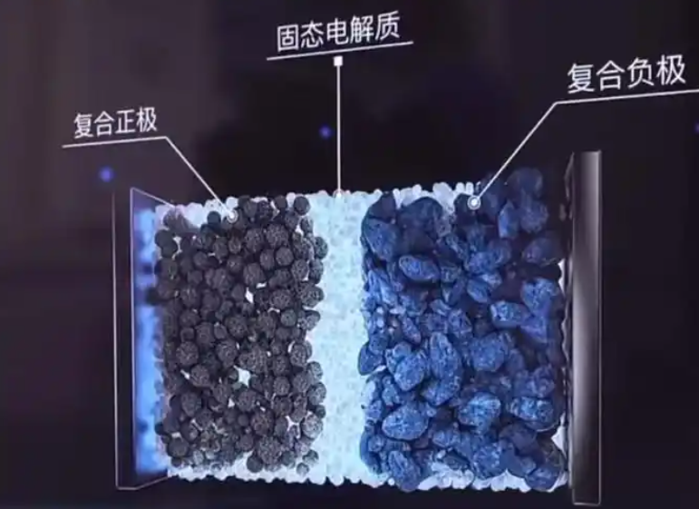
At the material level, the solid electrolyte cell community remains divided among three primary inorganic electrolyte families: sulfides, oxides, and halides. Each family offers a distinct combination of ionic conductivity, electrochemical stability, mechanical properties, and processability. I have summarized the core comparison in the table below. The numbers are representative ranges drawn from public literature and my own conversations with developers, not absolute limits. What matters is the pattern: no single solid electrolyte cell chemistry has yet solved all requirements simultaneously.
| Electrolyte family | Typical ionic conductivity | Thermal stability | Interface with lithium metal | Moisture sensitivity | Scalability outlook | Primary barrier for a solid electrolyte cell |
|---|---|---|---|---|---|---|
| Sulfide | 1–10 mS/cm | Poor | Reactive, interphase growth | Very high | Moderate | H2S generation and dry-room cost |
| Oxide | 0.1–1 mS/cm | Excellent | Generally stable but high resistance | Low | High | Grain-boundary and interfacial resistance |
| Halide | 0.5–10 mS/cm | Good | Promising with high-voltage cathodes | Moderate | Emerging | Anode interface and scalable synthesis |
| Polymer | 0.01–0.1 mS/cm | Moderate | Poor with lithium metal | Low | Very high | Low room-temperature conductivity |
| Composite | 0.1–5 mS/cm | Good | Tunable | Moderate | Moderate | Percolation and processing complexity |
Ionic conductivity is the most frequently cited metric for a solid electrolyte cell, but it is far from sufficient. The transport of ions through a solid electrolyte can be described by the Nernst–Einstein relation, which links conductivity to diffusivity:
$$D = \frac{k_B T \sigma}{n q^2}$$
Here, \(D\) is the diffusion coefficient, \(k_B\) is the Boltzmann constant, \(T\) is absolute temperature, \(\sigma\) is ionic conductivity, \(n\) is the carrier concentration, and \(q\) is the elementary charge. In a practical solid electrolyte cell, high bulk conductivity must be paired with low grain-boundary resistance and low interfacial resistance. The total resistance of a solid electrolyte cell can be approximated as:
$$R_{total} = R_{bulk} + R_{gb} + R_{interface} + R_{contact}$$
Each term can dominate depending on the material system and processing route. For sulfide electrolytes, bulk conductivity is often excellent, but interfacial reactions with lithium metal or high-voltage cathodes can rapidly increase \(R_{interface}\). For oxides, \(R_{gb}\) can be orders of magnitude higher than \(R_{bulk}\) unless sintering aids and optimized grain boundaries are used. For halides, the bulk and grain-boundary properties are attractive, but the anode interface remains a moving target. I have seen many promising solid electrolyte cell compositions fail not because of intrinsic conductivity, but because the interface resistance grew during cycling.
The activation energy for ion transport is another critical parameter. Arrhenius behavior is commonly used to model the temperature dependence of conductivity:
$$\sigma T = \sigma_0 \exp\left(-\frac{E_a}{k_B T}\right)$$
A low activation energy \(E_a\) means that a solid electrolyte cell can maintain useful conductivity at lower temperatures, which reduces the need for thermal management and improves cold-weather performance. Halide and sulfide systems often exhibit lower \(E_a\) than oxide systems, but they can also suffer from greater chemical reactivity. The trade-off between transport and stability is the central tension in solid electrolyte cell design.
During the summit, I noticed that halide electrolytes received considerable attention from researchers who prioritize high-voltage compatibility. One attractive claim is that certain amorphous or oxyhalide compositions can exceed 10 mS/cm at room temperature. If that value can be reproduced in a thick, defect-free membrane, it would be a major enabler for a solid electrolyte cell with high power density. However, I remain cautious because laboratory-scale conductivity measurements often use thin pellets with gold blocking electrodes, which do not fully represent the environment inside a real solid electrolyte cell. The presence of a lithium metal anode, a high-nickel cathode, and mechanical stack pressure can alter the transport pathways and trigger side reactions.
Silicon-based anodes were another major theme. A solid electrolyte cell can potentially use a silicon anode with a very high specific capacity. The theoretical capacity of silicon is approximately 4200 mAh/g, which is more than ten times that of graphite. But silicon undergoes massive volumetric expansion during lithiation:
$$\frac{\Delta V}{V_0} = \frac{V_{Li_xSi} – V_{Si}}{V_{Si}} \times 100\%$$
Experimental values for this expansion range from 300% to 400%, depending on the lithium content and the silicon morphology. In a conventional liquid-electrolyte cell, this expansion causes particle cracking, continuous solid-electrolyte interphase growth, and rapid capacity fade. In a solid electrolyte cell, the expansion creates an additional problem: it can fracture the solid electrolyte and destroy the mechanical integrity of the stack. Therefore, silicon anodes in a solid electrolyte cell require careful engineering of porosity, particle size, binder content, and stack pressure.
| Anode material | Theoretical capacity (mAh/g) | Volume change (%) | Compatibility with a solid electrolyte cell | Key challenge |
|---|---|---|---|---|
| Graphite | 372 | ~10 | Good | Limited energy density |
| Silicon | 4200 | 300–400 | Moderate | Mechanical fracture and contact loss |
| Silicon–carbon composite | 1000–2000 | 100–200 | Good | Uniform dispersion and cycle life |
| Lithium metal | 3860 | Infinite (plating) | High potential | Dendrite penetration and interfacial resistance |
| Lithium alloy | 500–2000 | 50–200 | Moderate | Alloy phase stability |
I have consistently argued that the success of a solid electrolyte cell will depend less on the anode’s initial capacity and more on the anode’s ability to maintain mechanical and electrochemical contact over thousands of cycles. A silicon anode in a solid electrolyte cell must be pre-lithiated or structured in a way that accommodates expansion without generating local stress concentrations. Several developers are exploring porous silicon, silicon nanowires, and silicon–carbon composites. Each approach has merits, but none has yet demonstrated the combination of high areal capacity, low stack pressure, and long cycle life required for automotive deployment.
Equipment and process technology are often underestimated in the solid electrolyte cell debate. The summit featured a detailed discussion of warm isostatic pressing, a process that applies elevated temperature and high pressure uniformly to a stacked cell assembly. The purpose is to densify the solid electrolyte layer, eliminate voids, and improve contact between the electrolyte and the electrodes. The relative density of a solid electrolyte cell component can be expressed as:
$$\rho_{rel} = \frac{\rho_{measured}}{\rho_{theoretical}} \times 100\%$$
Warm isostatic pressing can push \(\rho_{rel}\) above 95%, which is essential for reducing porosity-related resistance and preventing lithium dendrite initiation. The process also affects the microstructure of the solid electrolyte, the interfacial contact area, and the residual stress state. I have seen data suggesting that a well-designed warm isostatic pressing step can increase the critical current density of a solid electrolyte cell by a factor of two or more, simply by removing defects that would otherwise concentrate electric fields.
| Process parameter | Typical range | Effect on a solid electrolyte cell | Risk if out of range |
|---|---|---|---|
| Temperature | 80–150 °C | Softens binder, enhances particle rearrangement | Electrolyte decomposition or cathode degradation |
| Pressure | 50–300 MPa | Collapses voids, increases contact area | Fracture of brittle electrolyte or current collector |
| Hold time | 1–30 min | Allows creep and densification | Throughput penalty or over-sintering |
| Cooling rate | 1–10 °C/min | Controls residual stress | Thermal shock and microcracking |
| Atmosphere | Dry air or inert | Prevents moisture and oxygen attack | Surface contamination and impedance rise |
A solid electrolyte cell also requires a fundamentally different manufacturing flow compared with a liquid-electrolyte cell. The absence of a liquid electrolyte means that there is no spontaneous wetting of pores. Every interface must be formed by mechanical contact, sintering, or a combination of both. This changes the role of the separator, the binder, and the stacking process. In a conventional cell, the separator is a porous membrane that physically separates the electrodes while allowing ion transport through a liquid. In a solid electrolyte cell, the separator is replaced by a dense solid electrolyte membrane that must be thin, defect-free, and mechanically robust. Producing such a membrane at high speed and low cost is one of the hardest engineering challenges I have encountered in the battery field.
The global competitive landscape can be summarized by regional strategies. China is pursuing a semi-solid-first approach, where a small amount of liquid electrolyte is retained to improve interfacial contact, while the majority of the electrolyte is solid. This allows manufacturers to use existing lithium-ion production equipment with modifications, achieve incremental energy density gains, and learn about solid-state interfaces at scale. Japan and Korea are focusing on full-solid-state cells, often with sulfide electrolytes and lithium metal anodes. Their goal is a step-change in energy density and safety. North America has a diverse mix of startups and automakers, with some pursuing oxide-based solid electrolyte cells and others developing halide or sulfide systems. Europe is strong in equipment, characterization, and automotive integration, but it lacks a large-scale cell manufacturing base for solid electrolyte cells.
| Region | Primary strategy | Dominant electrolyte focus | Anode focus | Manufacturing approach | Key advantage | Key vulnerability |
|---|---|---|---|---|---|---|
| China | Semi-solid first, then full solid | Oxide, composite, polymer | Graphite, silicon–carbon | Retrofitted lithium-ion lines | Complete supply chain and cost control | Dependence on liquid electrolyte for interfaces |
| Japan | Full solid-state leapfrog | Sulfide | Lithium metal, silicon | New dry-room lines | Deep materials research and automotive integration | High cost and sulfide handling |
| Korea | Full solid-state scale-up | Sulfide, oxide | Lithium metal, silicon | Pilot to gigafactory | Strong battery manufacturing experience | Supply chain for critical materials |
| United States | Innovation-driven, mixed | Oxide, halide, sulfide | Lithium metal, silicon | Startup-led pilot lines | Venture ecosystem and advanced characterization | Limited domestic manufacturing base |
| Europe | Equipment and integration | Oxide, polymer, composite | Silicon, lithium metal | Research fab and partnerships | High-pressure processing and metrology | Cell manufacturing scale |
I have observed that the term “solid electrolyte cell” is sometimes used loosely to describe cells with gel or quasi-solid electrolytes. In my analysis, a true solid electrolyte cell should have an electrolyte with an ionic conductivity that is predominantly due to solid-state transport, not liquid-phase diffusion. The distinction matters because the failure modes, manufacturing requirements, and safety profiles are fundamentally different. A semi-solid cell may offer a shorter path to market, but it does not eliminate the flammable liquid entirely. A full solid electrolyte cell, by contrast, can potentially remove the flammable liquid, enable lithium metal anodes, and simplify thermal management. However, it also introduces new failure modes such as dendrite penetration, void formation, and mechanical fracture.
The economic challenge is formidable. The cost of a solid electrolyte cell per kilowatt-hour can be decomposed into material cost, processing cost, yield loss, and capital depreciation:
$$C_{kWh} = \frac{C_{material} + C_{process} + C_{yield loss} + C_{capital}}{E_{pack}}$$
Here, \(E_{pack}\) is the usable energy of the pack. For a solid electrolyte cell to compete with conventional lithium-ion cells, every term in the numerator must be reduced while \(E_{pack}\) is increased. Material costs for sulfide electrolytes are high because of the need for high-purity precursors and dry-room processing. Processing costs for warm isostatic pressing and dry-room assembly are also significant. Yield loss can be severe because a single defect in a solid electrolyte membrane can short-circuit the entire cell. Capital costs are high because the equipment for solid electrolyte cell production is not yet standardized. I have seen estimates suggesting that the first generation of full solid electrolyte cells will cost two to three times more per kilowatt-hour than advanced liquid-electrolyte cells. Closing that gap will require both material innovations and manufacturing scale.
| Cost category | Share of total cost for a solid electrolyte cell | Main drivers | Potential reduction pathway |
|---|---|---|---|
| Solid electrolyte material | 20–35% | Precursor purity, synthesis energy, rare elements | Lower-cost synthesis, abundant elements, recycling |
| Anode material | 10–20% | Lithium metal or silicon processing | Thin lithium foils, silicon–carbon composites |
| Cathode material | 15–25% | High-nickel content, coating, interface engineering | Reduced cobalt, optimized coating |
| Processing and equipment | 20–30% | Dry room, isostatic pressing, stacking | Higher throughput, automation, in-line metrology |
| Yield loss and scrap | 5–15% | Membrane defects, interfacial contamination | Statistical process control, defect detection |
| Capital depreciation | 10–20% | Low utilization, expensive tooling | Gigafactory scale, standardized equipment |
Performance targets for a solid electrolyte cell are equally demanding. Automotive requirements typically include an energy density above 400 Wh/kg at the cell level, a cycle life exceeding 1000 cycles to 80% capacity retention, a fast-charge capability of 10–80% in under 20 minutes, and a wide operating temperature range. The capacity retention of a solid electrolyte cell can be modeled as:
$$Q_n = Q_0 \left(1 – k n\right)$$
where \(Q_n\) is the capacity after \(n\) cycles, \(Q_0\) is the initial capacity, and \(k\) is a degradation rate constant. For a solid electrolyte cell, \(k\) is often dominated by interfacial resistance growth, particle cracking, or lithium inventory loss. Improving the mechanical properties of the solid electrolyte and the electrode composites can reduce \(k\). However, there is a trade-off: harder electrolytes are more resistant to dendrites but more prone to fracture; softer electrolytes can accommodate expansion but may creep under stack pressure. I have seen promising data from composite electrolytes that combine a rigid oxide skeleton with a soft polymer or halide filler. These composites can achieve a balance of mechanical strength and interfacial compliance, but their manufacturing complexity is high.
The coulombic efficiency of a solid electrolyte cell is another key indicator:
$$CE = \frac{Q_{discharge}}{Q_{charge}} \times 100\%$$
A coulombic efficiency below 99.9% in a lithium metal solid electrolyte cell usually indicates continuous side reactions or dendrite growth. Even a small inefficiency can rapidly consume the lithium inventory and dry out the cell. Therefore, any commercial solid electrolyte cell must demonstrate extremely high coulombic efficiency, ideally above 99.95%, over hundreds of cycles. This is a very high bar, and it explains why so many laboratory results do not translate to commercial prototypes.
The global standards landscape is also evolving. A new vehicle solid-state battery standard took effect in 2026, providing definitions, test methods, and safety requirements for solid electrolyte cells. This is a critical step because it creates a common language for automakers, suppliers, and regulators. Without standards, every developer uses different test protocols, making it impossible to compare performance claims. I expect the standard to accelerate investment by reducing uncertainty. It will also force developers to be more transparent about their cell chemistry, stack pressure, and operating conditions. A solid electrolyte cell that performs well only under unusually high stack pressure or narrow temperature windows will be less attractive once standardized testing reveals its limitations.
| Standard category | Scope | Impact on a solid electrolyte cell |
|---|---|---|
| Terminology and classification | Defines semi-solid, quasi-solid, and full solid | Prevents greenwashing and clarifies performance claims |
| Safety testing | Thermal runaway, nail penetration, overcharge | Highlights advantages of a solid electrolyte cell |
| Performance testing | Energy density, power density, cycle life | Enables apples-to-apples comparison |
| Durability testing | Temperature cycling, vibration, humidity | Exposes mechanical weaknesses in a solid electrolyte cell |
| Recycling and sustainability | Material recovery, carbon footprint | Drives design for disassembly and low-cost materials |
Several automakers have announced pilot lines and production timelines. One major Japanese automaker completed prototype testing of a vehicle-grade solid electrolyte cell on a pilot line in 2026 and aims to launch an electric vehicle with a self-developed solid electrolyte cell in the 2028 fiscal year. Another Japanese automaker plans to conduct small-batch vehicle validation in 2027 using a sulfide-based solid electrolyte cell. A Korean battery maker plans to start mass production of a full solid electrolyte cell in 2027. Chinese battery and vehicle companies have been rapidly building pilot lines for semi-solid and solid electrolyte cells, supported by the new standard and strong domestic demand. These timelines are ambitious, but I have learned to treat them with caution. Pilot-line success does not guarantee mass-production success. The transition from a hand-built prototype to a high-yield, high-volume line is where many programs fail.
| Announced milestone | Year | Cell type | Region | My assessment of feasibility |
|---|---|---|---|---|
| Pilot-line prototype testing completed | 2026 | Full solid electrolyte cell | Japan | Plausible for small volumes |
| Vehicle standard takes effect | 2026 | All solid-state categories | China | High likelihood |
| Small-batch vehicle validation | 2027 | Full solid electrolyte cell | Japan | Moderate likelihood |
| Mass production start | 2027 | Full solid electrolyte cell | Korea | Aggressive but possible for limited volumes |
| Vehicle launch with self-developed cell | 2028 | Full solid electrolyte cell | Japan | Moderate likelihood |
| Broad commercial deployment | 2030+ | Full solid electrolyte cell | Global | Depends on cost and yield breakthroughs |
I have repeatedly emphasized that the solid electrolyte cell is not a single product but a family of technologies. A sulfide-based solid electrolyte cell behaves differently from an oxide-based solid electrolyte cell, and a halide-based solid electrolyte cell behaves differently again. Even within one family, the choice of cathode, anode, binder, conductive additive, and stack pressure can change performance by an order of magnitude. Therefore, broad claims such as “solid-state batteries will cost less than liquid-electrolyte batteries by 2030” are not useful without specifying the chemistry, format, and manufacturing process. I prefer to evaluate a solid electrolyte cell using a multidimensional scorecard that includes ionic conductivity, interfacial stability, mechanical resilience, processability, cost, and safety.
| Dimension | Metric | Target for automotive solid electrolyte cell | Current state of the art | Gap |
|---|---|---|---|---|
| Ionic conductivity | Bulk conductivity at 25 °C | >5 mS/cm | 1–10 mS/cm for sulfides and halides | Small for bulk, large for grain boundaries |
| Interfacial resistance | Area-specific resistance | <10 Ω·cm² | 20–200 Ω·cm² | Large |
| Mechanical resilience | Fracture toughness | >1 MPa·m¹/² | 0.5–1.5 MPa·m¹/² | Moderate |
| Cycle life | Cycles to 80% capacity | >1000 | 200–800 | Large |
| Areal capacity | mAh/cm² | >3 | 2–4 | Moderate |
| Cost | USD/kWh at pack level | <100 | 150–300 | Large |
| Safety | Pass nail penetration without fire | Required | Chemistry-dependent | Promising but not universal |
The interface between the solid electrolyte and the cathode is particularly challenging. During charging, the cathode expands and contracts. If the solid electrolyte is rigid, the interface can delaminate or crack. If the solid electrolyte is soft, it may creep into the cathode pores but also deform under pressure. A common strategy is to apply a cathode coating, such as lithium niobate or a lithium phosphate, to suppress interfacial reactions. The effect of the coating can be modeled as a reduction in the interfacial resistance:
$$R_{interface} = \frac{\rho_{coating}}{A} + R_{charge transfer}$$
where \(\rho_{coating}\) is the specific resistance of the coating and \(A\) is the contact area. A thin, conformal coating can reduce side reactions without significantly increasing resistance. However, applying a uniform coating on high-nickel cathode particles at scale is not trivial. I have seen promising results from atomic layer deposition and wet-chemical coating, but both add cost and complexity to the solid electrolyte cell manufacturing flow.
Dendrite formation is another persistent failure mode. In a solid electrolyte cell, lithium metal can plate unevenly and penetrate through grain boundaries, pores, or cracks. The critical current density at which dendrites form depends on the electrolyte’s shear modulus, the stack pressure, and the interfacial defect density. A simplified criterion for dendrite suppression is:
$$G_{electrolyte} > \frac{\sigma_{lithium}^2}{2 \pi \gamma_{interface}}$$
where \(G_{electrolyte}\) is the shear modulus of the solid electrolyte, \(\sigma_{lithium}\) is the local stress in lithium, and \(\gamma_{interface}\) is the interfacial energy. This relationship suggests that a stiffer solid electrolyte is better at suppressing dendrites. But a stiffer electrolyte is also more prone to fracture. The design window is narrow, and it depends on the exact chemistry and microstructure. I believe that composite electrolytes with a stiff skeleton and a compliant grain-boundary phase may offer the best compromise, but their long-term stability under repeated cycling is still unproven.
The role of stack pressure in a solid electrolyte cell cannot be overstated. Unlike a liquid-electrolyte cell, which maintains contact through capillary forces, a solid electrolyte cell relies on externally applied pressure to maintain interfacial contact. Typical stack pressures range from 1 MPa to 10 MPa for oxide-based cells and can be lower for sulfide-based cells with soft mechanical properties. However, applying high pressure to a large format cell requires robust cell design and module engineering. The pressure vessel adds weight, volume, and cost. Therefore, reducing the required stack pressure is a major goal for solid electrolyte cell developers. One approach is to use a compliant interlayer that can accommodate volume changes without losing contact. Another is to design the cell stack with a slight excess of lithium or a porous anode host that maintains contact during cycling.
| Stack pressure range | Effect on a solid electrolyte cell | Engineering implication |
|---|---|---|
| <1 MPa | Insufficient contact, high interfacial resistance | Requires very compliant interfaces |
| 1–5 MPa | Good contact, moderate dendrite suppression | Manageable with module design |
| 5–10 MPa | Low resistance, strong dendrite suppression | Heavy and costly pressure hardware |
| >10 MPa | Potential electrolyte fracture and creep | Not practical for large packs |
I have also been watching the development of dry electrode processing. In a conventional lithium-ion cell, the electrode slurry is cast from a solvent and dried. In a solid electrolyte cell, solvent-based processing can be problematic because the solid electrolyte may react with moisture or dissolve. Dry processing mixes active material, conductive additive, and binder without solvent, then fibrillates the binder into a network. This approach can reduce energy consumption, eliminate drying ovens, and improve compatibility with moisture-sensitive solid electrolytes. However, dry processing requires precise control of particle size, mixing energy, and fibrillation temperature. The resulting electrode must have sufficient mechanical strength and ionic conductivity. I see dry processing as a key enabler for low-cost solid electrolyte cell manufacturing, but it is still in an early stage of industrialization.
The supply chain for a solid electrolyte cell is another bottleneck. Sulfide electrolytes require high-purity lithium sulfide, phosphorus pentasulfide, and other precursors. These materials are not produced at scale today. Halide electrolytes require anhydrous metal halides and careful handling. Oxide electrolytes require high-temperature sintering, which consumes energy and can lead to lithium loss. Lithium metal anodes require ultra-thin foils or in-situ plating hosts. Silicon anodes require high-purity silicon and advanced composite engineering. Each of these supply chains must mature before a solid electrolyte cell can be produced at gigawatt-hour scale. I have seen estimates that the solid electrolyte cell supply chain will require tens of billions of dollars of investment over the next decade. Without coordinated investment from automakers, battery makers, material suppliers, and governments, the scale-up will be slower than the announced timelines suggest.
| Material | Current supply chain maturity | Scaling challenge for a solid electrolyte cell | Potential timeline to maturity |
|---|---|---|---|
| Lithium sulfide | Laboratory scale | Moisture sensitivity, high purity | 2028–2030 |
| Phosphorus pentasulfide | Small commercial | Hazardous handling, limited capacity | 2027–2029 |
| Lanthanum zirconium oxide | Pilot scale | Sintering energy, grain boundary control | 2026–2028 |
| Lithium metal foil | Early commercial | Thin gauges, surface protection | 2027–2030 |
| Silicon–carbon composite | Commercial for liquid cells | Adaptation to solid electrolyte cell | 2026–2028 |
| Halide electrolytes | Laboratory scale | Synthesis, anode interface | 2029–2032 |
Despite these challenges, I remain optimistic about the long-term trajectory of the solid electrolyte cell. The fundamental advantages are too compelling to ignore: higher energy density, improved safety, faster charging, and a wider operating temperature range. The question is not whether the solid electrolyte cell will eventually succeed, but which applications will adopt it first. I believe the first commercial deployments will be in premium electric vehicles, where high energy density and fast charging justify a cost premium. As manufacturing scales and yields improve, the solid electrolyte cell will move downmarket into mass-market vehicles, consumer electronics, and stationary storage. The transition will be gradual, with semi-solid cells filling the gap in the near term and full solid electrolyte cells taking over in the long term.
I have often said that the solid electrolyte cell is a system-level technology, not just a materials technology. It requires advances in electrolyte chemistry, electrode engineering, stack design, manufacturing equipment, testing protocols, and recycling. A breakthrough in one area alone is not enough. For example, a new solid electrolyte with record conductivity is useless if it cannot be coated onto a cathode without cracking. A high-capacity silicon anode is useless if it expands and destroys the stack. A fast manufacturing process is useless if it produces defects that cause short circuits. Therefore, the winners in the solid electrolyte cell race will be those who can integrate multiple innovations into a reliable, scalable, and cost-effective product.
Based on my analysis, I have developed a set of conditions that must be met for a solid electrolyte cell to achieve widespread adoption. First, the cell must deliver at least 400 Wh/kg and 1000 Wh/L at the cell level. Second, it must achieve more than 1000 cycles to 80% capacity retention with a coulombic efficiency above 99.9%. Third, it must operate at stack pressures below 5 MPa and temperatures from -20 °C to 60 °C. Fourth, it must pass standard safety tests without fire or explosion. Fifth, it must be produced at a cost below 100 USD/kWh at the pack level. Sixth, it must have a supply chain that can support at least 100 GWh per year. These conditions are demanding, but they are not impossible. I expect the first commercial cells to meet some but not all of these conditions. The first generation will likely be expensive and limited in volume. The second generation will improve cost and scale. The third generation will achieve mass-market parity.
| Generation | Timeline | Energy density | Cycle life | Stack pressure | Cost | Primary application |
|---|---|---|---|---|---|---|
| Gen 1 | 2026–2028 | 300–400 Wh/kg | 500–1000 | 5–10 MPa | 150–300 USD/kWh | Premium EV, demonstration |
| Gen 2 | 2028–2030 | 400–500 Wh/kg | 1000–1500 | 3–5 MPa | 100–150 USD/kWh | Premium and mid-range EV |
| Gen 3 | 2030–2035 | >500 Wh/kg | >1500 | <3 MPa | <100 USD/kWh | Mass-market EV, eVTOL, storage |
The semi-solid cell deserves special attention because it is often dismissed as a compromise. In my view, a semi-solid cell is a smart transitional strategy. It retains a small amount of liquid electrolyte to ensure interfacial contact, while using a solid or gel-like electrolyte to improve safety and enable higher-voltage cathodes. The liquid content can be reduced over successive generations, gradually approaching a full solid electrolyte cell. This path allows manufacturers to learn about solid-state interfaces, test new materials, and build customer confidence without waiting for a complete technology leap. It also allows existing lithium-ion factories to be upgraded rather than replaced. I expect semi-solid cells to capture a significant share of the premium EV market before full solid electrolyte cells take over.
One of the most interesting debates at the summit was whether a solid electrolyte cell should use a lithium metal anode or a silicon-based anode. Lithium metal offers the highest energy density but suffers from dendrites and interfacial instability. Silicon offers high capacity but suffers from volume expansion. A hybrid approach uses a silicon–carbon anode with a small amount of lithium metal, or a lithium metal anode with a protective silicon interlayer. I have seen data showing that a thin silicon layer can protect the solid electrolyte from direct contact with lithium metal, reducing interfacial reactions. However, the silicon layer must be thin and uniform, which adds manufacturing complexity. Another approach is to use a lithium alloy, such as lithium–indium or lithium–tin, which has a higher potential but better stability. The trade-off is lower cell voltage and energy density. I believe there is no universal answer; the optimal anode will depend on the application, the electrolyte, and the manufacturing process.
The cathode side is equally important. To achieve high energy density, a solid electrolyte cell needs a high-capacity cathode, such as a high-nickel layered oxide or a lithium-rich material. These cathodes operate at high voltages, which can oxidize the solid electrolyte. Halide electrolytes are particularly attractive because they can withstand high voltages, but they may react with the anode. Oxide electrolytes are stable at high voltages but have high interfacial resistance. Sulfide electrolytes have high conductivity but are easily oxidized. Therefore, a common strategy is to use a cathode coating or a buffer layer to protect the solid electrolyte. The coating must be chemically stable, ionically conductive, and mechanically compliant. This is a tall order, and it explains why cathode–electrolyte interfaces remain a major focus of research.
| Cathode material | Capacity (mAh/g) | Voltage (V vs. Li/Li+) | Compatibility with a solid electrolyte cell | Key challenge |
|---|---|---|---|---|
| NMC 811 | 200–220 | 3.7 | Moderate | Interfacial oxidation of sulfide |
| NCA | 200–220 | 3.7 | Moderate | Similar to NMC |
| Lithium-rich layered oxide | 250–300 | 3.6 | Low to moderate | Voltage fade and oxygen release |
| High-voltage spinel | 130–150 | 4.7 | Good with halides | Manganese dissolution |
| Sulfur | 1675 | 2.1 | Promising but complex | Polysulfide shuttle and volume change |
I have also been monitoring the progress of computational modeling in the solid electrolyte cell field. Density functional theory, molecular dynamics, and finite element analysis are now routinely used to screen electrolyte compositions, predict interfacial reactions, and optimize stack design. For example, the electrochemical stability window of a solid electrolyte can be estimated from the calculated energies of decomposition products:
$$\Delta G_{decomp} = G_{products} – G_{reactants}$$
If \(\Delta G_{decomp}\) is negative over the operating voltage range, the electrolyte is thermodynamically unstable and will decompose. However, kinetic factors can prevent decomposition, so thermodynamic predictions must be validated experimentally. Machine learning is also being used to accelerate the discovery of new solid electrolytes with high conductivity and low activation energy. I have seen promising results from generative models that propose novel compositions, but experimental validation remains the bottleneck. It takes months or years to synthesize and test a new solid electrolyte, so the feedback loop is slow. I expect computational screening to become more valuable as experimental data sets grow and as automated synthesis platforms mature.
The environmental and social dimensions of the solid electrolyte cell are also worth considering. A solid electrolyte cell may use fewer critical materials such as cobalt and nickel if it enables lithium metal or high-voltage cathodes. However, it may use more lithium, lanthanum, germanium, or indium. Recycling a solid electrolyte cell is more complex than recycling a liquid-electrolyte cell because the solid electrolyte must be separated from the electrodes without contamination. The current recycling infrastructure is not designed for solid electrolyte cells. Therefore, design for recycling must be integrated into the product development process from the beginning. I believe that a circular economy for solid electrolyte cells is possible, but it will require new separation technologies, new business models, and new regulations.
| Recycling aspect | Liquid-electrolyte cell | Solid electrolyte cell | Implication |
|---|---|---|---|
| Electrolyte separation | Solvent extraction | Mechanical or thermal separation | Higher energy cost |
| Cathode recovery | Hydrometallurgical | Similar but affected by coating | Coating removal step needed |
| Anode recovery | Graphite or silicon | Lithium metal or silicon | Lithium metal is reactive |
| Solid electrolyte recovery | Not applicable | Difficult due to mixed phases | Low-value stream |
| Safety during recycling | Fire risk from residual charge | Dendrite and moisture risk | Requires inert atmosphere |
In my assessment, the solid electrolyte cell race will be decided not by a single breakthrough but by the accumulation of many small improvements. The companies that succeed will be those that can iterate quickly, learn from failures, and integrate materials, processes, and systems. I have seen too many programs fail because they focused on a single metric, such as ionic conductivity, and ignored the system-level requirements. The most successful teams I have observed are those that combine deep materials expertise with strong manufacturing engineering and a clear understanding of customer needs. They do not chase the highest conductivity at any cost; they optimize for the best overall solution.
The global solid electrolyte cell competition is also shaped by policy and investment. Governments in Asia, Europe, and North America are funding research, pilot lines, and supply-chain development. These investments are essential because the private sector alone cannot bear the risk of pre-commercial manufacturing. However, I worry about duplication and fragmentation. If every region tries to build a complete supply chain for a solid electrolyte cell, the result could be excess capacity and wasted resources. Greater international collaboration on pre-competitive research, standards, and recycling could accelerate progress for everyone. At the same time, competition drives innovation, and no region wants to be dependent on another for a strategic technology. The balance between collaboration and competition will shape the pace of the solid electrolyte cell transition.
Looking ahead, I expect the next three years to be decisive. By 2027, we will see the first small-batch vehicle deployments of full solid electrolyte cells. By 2028, we will have real-world data on cycle life, safety, and cost. By 2030, the first mass-market solid electrolyte cell vehicles may appear, but they will likely be limited to premium segments. The solid electrolyte cell will not replace the liquid-electrolyte cell overnight. Instead, it will coexist and gradually gain share, starting with applications that value energy density, safety, and fast charging. I am confident that the solid electrolyte cell will eventually become a mainstream technology, but I am also realistic about the challenges. The race is a marathon, not a sprint, and the winners will be those who can sustain investment, learn from data, and execute at scale.
To summarize my current view, I have compiled a final scorecard for the solid electrolyte cell across different dimensions. This scorecard reflects my judgment based on public information and industry interactions. It is not a prediction of any specific company’s success, but a framework for evaluating progress.
| Dimension | Current status | 2028 outlook | 2030 outlook | Confidence |
|---|---|---|---|---|
| Ionic conductivity | Sufficient for many applications | Improved grain-boundary control | Widely sufficient | High |
| Interfacial resistance | Major bottleneck | Reduced by coatings and composites | Manageable at scale | Moderate |
| Anode stability | Lithium metal and silicon both challenged | Protective layers and hosts | Reliable long-life anodes | Moderate |
| Cathode compatibility | High-voltage issues | Halide and coated cathodes | Broad compatibility | Moderate |
| Manufacturing yield | Low | Pilot-line learning | Commercial yield | Moderate |
| Cost | High | Declining | Approaching parity | Low to moderate |
| Supply chain | Immature | Early scale-up | Mature for key materials | Moderate |
| Safety | Promising | Validated by standards | Superior to liquid cells | High |
| Recycling | Underdeveloped | Pilot programs | Closed-loop potential | Low |
I will continue to track the solid electrolyte cell race with great interest. The technology has the potential to transform transportation, energy storage, and consumer electronics. But realizing that potential will require patience, investment, and a willingness to solve hard problems across materials, manufacturing, and systems. The solid electrolyte cell is not a magic bullet; it is a complex engineered system that must be optimized as a whole. I believe that the organizations that embrace this complexity will be the ones that lead the next generation of energy storage.